

Next: Receiver Cable interpolation
Up: Curry: Interpolating diffracted multiples
Previous: Data Description
The most tractable problem for this data and also the most commonly shown
interpolation result is increasing the number of shots by a factor of 2. This
will result in a source distribution where the flip and flop shots for a given
in-line position are both present. While the desired goal for this data is to
increase the in-line source sampling by a factor of 3, interpolating by a
factor of 2 does have the benefit of decreasing the cross-line density requirement
by a factor of 2, and also results in having pairs of shots with relatively
dense (25m) sampling in the cross-line direction. This is a big step up from
the 200m between sail lines.
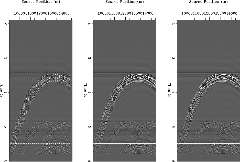
Results for an increase in shots by a factor of two are shown in Figure
![[*]](http://sepwww.stanford.edu/latex2html/cross_ref_motif.gif) . The panel on the left corresponds to the input data, which is
in this case a common receiver gather. The missing traces correspond to missing
"flip" shots. The panel in the center of the figure corresponds to a 2D
PEF-based interpolation, while the panel on the right corresponds to a 3D
PEF-based interpolation, where the PEF is estimated along the receiver cable as
well as across the source and time axes. There are only minimal differences between
the 2D and 3D results. This is because the 2D result is actually quite good,
and shows that an overly computationally intensive method is not necessary for
this problem.
. The panel on the left corresponds to the input data, which is
in this case a common receiver gather. The missing traces correspond to missing
"flip" shots. The panel in the center of the figure corresponds to a 2D
PEF-based interpolation, while the panel on the right corresponds to a 3D
PEF-based interpolation, where the PEF is estimated along the receiver cable as
well as across the source and time axes. There are only minimal differences between
the 2D and 3D results. This is because the 2D result is actually quite good,
and shows that an overly computationally intensive method is not necessary for
this problem.
flipflopx2
Figure 2 Flip-flop interpolation of a common-receiver-section (offset=1250m). From left to
right: original input common-receiver gather; result of 2D interpolation;
result of 3D interpolation.
![[*]](http://sepwww.stanford.edu/latex2html/movie.gif)


Now that the factor of 2 shot interpolation has been shown to be relatively
insensitive to the dimensionality of the interpolation, this same test is
repeated for increasing the shot sampling by a factor of 3, which would
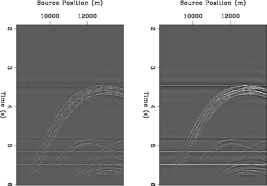
correspond to the ideal output. The results are shown in Figure ![[*]](http://sepwww.stanford.edu/latex2html/cross_ref_motif.gif) .
The interpolation is not nearly as good as for the case with the factor of 2.
This is in part due to the increased expansion of the PEF coefficients that is
required, and thus the approximation that the filter is scale-invariant becomes less
valid.
.
The interpolation is not nearly as good as for the case with the factor of 2.
This is in part due to the increased expansion of the PEF coefficients that is
required, and thus the approximation that the filter is scale-invariant becomes less
valid.
flipflopx3
Figure 3 Flip-flop interpolation, factor of 3.
From left to right: original input common-receiver gather; result of 2D
interpolation.
![[*]](http://sepwww.stanford.edu/latex2html/movie.gif)


Increasing the dimensionality of the interpolation in this case appears to have
more effect than in the previous factor of 2 case.


Next: Receiver Cable interpolation
Up: Curry: Interpolating diffracted multiples
Previous: Data Description
Stanford Exploration Project
4/5/2006
![[*]](http://sepwww.stanford.edu/latex2html/cross_ref_motif.gif) . The panel on the left corresponds to the input data, which is
in this case a common receiver gather. The missing traces correspond to missing
"flip" shots. The panel in the center of the figure corresponds to a 2D
PEF-based interpolation, while the panel on the right corresponds to a 3D
PEF-based interpolation, where the PEF is estimated along the receiver cable as
well as across the source and time axes. There are only minimal differences between
the 2D and 3D results. This is because the 2D result is actually quite good,
and shows that an overly computationally intensive method is not necessary for
this problem.
. The panel on the left corresponds to the input data, which is
in this case a common receiver gather. The missing traces correspond to missing
"flip" shots. The panel in the center of the figure corresponds to a 2D
PEF-based interpolation, while the panel on the right corresponds to a 3D
PEF-based interpolation, where the PEF is estimated along the receiver cable as
well as across the source and time axes. There are only minimal differences between
the 2D and 3D results. This is because the 2D result is actually quite good,
and shows that an overly computationally intensive method is not necessary for
this problem.

![[*]](http://sepwww.stanford.edu/latex2html/movie.gif)
