Next: Discussion
Up: Dipping water-bottom
Previous: Water-bottom multiple
Figure ![[*]](http://sepwww.stanford.edu/latex2html/cross_ref_motif.gif) shows the raypath of a diffracted multiple
from a dipping reflector. The image-space coordinates of the diffracted
multiple are given by the same equations as the water-bottom multiple,
i.e. equations 32-34. The main
difference is that now
shows the raypath of a diffracted multiple
from a dipping reflector. The image-space coordinates of the diffracted
multiple are given by the same equations as the water-bottom multiple,
i.e. equations 32-34. The main
difference is that now  . In fact,
  depends exclusively oh the position of the diffractor with respect to the
receiver and is given by (Appendix E)
depends exclusively oh the position of the diffractor with respect to the
receiver and is given by (Appendix E)
| ![\begin{displaymath}
\alpha_r=\tan^{-1}\left[\frac{h_D+m_D-X_{diff}}{Z_{diff}}\right].\end{displaymath}](img84.gif) |
(47) |
mul_sktch6
Figure 14 Diffracted multiple from a
dipping water-bottom. Note that the receiver ray does not satisfy Snell's
law at the diffractor.
|
| 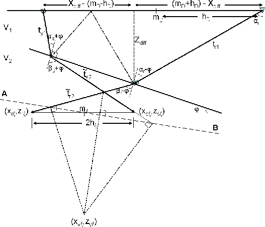 |

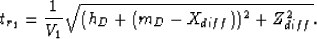
The depth of the diffractor Zdiff can be computed as (Appendix E):
|  |
(48) |
where  , as before, is the perpendicular distance between the CMP
and the reflector. It can be computed from the traveltime of the diffracted
multiple of the zero surface-offset trace as shown in Appendix E.
The traveltime segments from the source to the diffractor are the same
as before and given by equations 39-41, while
the traveltime from the diffractor to the receiver is simply
, as before, is the perpendicular distance between the CMP
and the reflector. It can be computed from the traveltime of the diffracted
multiple of the zero surface-offset trace as shown in Appendix E.
The traveltime segments from the source to the diffractor are the same
as before and given by equations 39-41, while
the traveltime from the diffractor to the receiver is simply
|  |
(49) |
In order to have the image coordinates entirely in terms of the data space
coordinates all that is left is to compute  (Appendix E):
| ![\begin{displaymath}
\alpha_s=\sin^{-1}\left[\frac{2\tilde{Z}_D\sin\varphi+(h_D+X...
...V_1t_m-\sqrt{(h_D+m_D-X_{diff})^2+Z_{diff}^2}}\right]-2\varphi.\end{displaymath}](img87.gif) |
(50) |
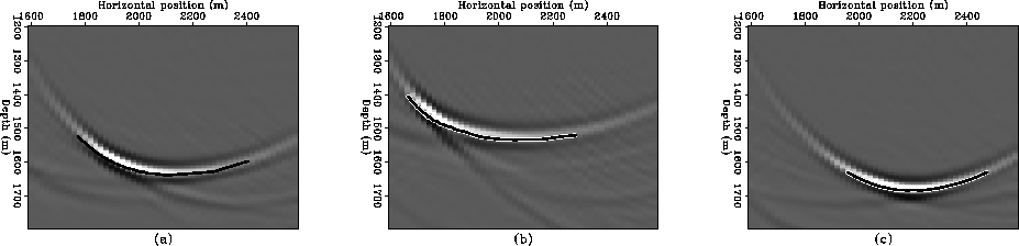
image4
Figure 15 image sections at 0, -200 and 200 m
subsurface offset for a diffracted multiple from a dipping water-bottom.


Figure shows three image sections at subsurface offsets
of 0, -200 and 200 m. These sections are a poor representation of either
the reflector or the diffractor since the diffracted multiple is not
imaged as a primary.
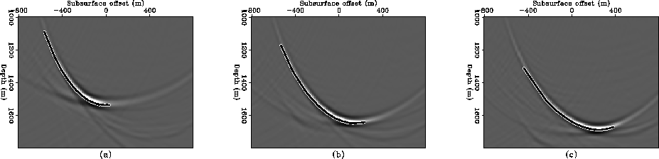
odcig4
Figure 16 SODCIGs at three different CMP
locations: 1,800, 2,000 and 2,200 m for a diffracted multiple from a dipping
water-bottom.
Figure shows three SODCIGs at CMP locations 1800, 2200 and
2600 m. Again, we see that the SODCIGs are very different depending on their
relative position to the diffractor, unlike the situation with the
non-diffracted multiple which maps to negative subsurface offsets
(for  ) for all SODCIGs.
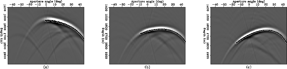
adcig4
Figure 17 ADCIGs corresponding to the three
SODCIGs of Figure .
The aperture angle and the image depth of the diffracted multiple in ADCIGs
can also be computed with equations 11 and 12 with
 and
and  given by equation 46.
Figure shows the ADCIG corresponding to the same ODCIG
in Figure . Again, notice that the apex is shifted away from
zero
aperture angle.
given by equation 46.
Figure shows the ADCIG corresponding to the same ODCIG
in Figure . Again, notice that the apex is shifted away from
zero
aperture angle.
Next: Discussion
Up: Dipping water-bottom
Previous: Water-bottom multiple
Stanford Exploration Project
11/1/2005