


| |
(29) |
To test the theory under realistic and diverse anisotropic conditions, in the numerical examples I used three sets of anisotropic Thomsen parameters representing three different rocks described by Tsvankin (2001):
The GreenLight River Shale is derived from the Green River Shale described by Tsvankin (2001) by halving the anisotropic parameters (
The first set of numerical experiments tests
the RMO equation with uniform scaling of velocity
expressed in equation 20.
In addition to the three anisotropic cases described above,
this RMO function is tested also for the special case of isotropic
velocity.
The second set tests
the generalized RMO functions expressed
in equations 24-26.
Only the three anisotropic cases are tested because
there is no meaningful isotropic case to test the generalized RMO function.
In all the synthetic-data examples I plot the correct RMO curve
computed by applying either equation 18
or equations 24-26,
and the approximate RMO curve computed
using
an ``isotropic'' approximation
and ignoring the distinction between the group aperture angle ![]() and the phase aperture angle
and the phase aperture angle ![]() .
.
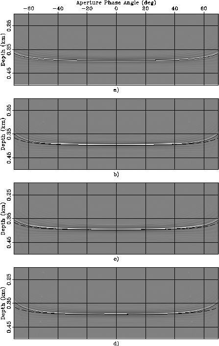
Figure ![[*]](http://sepwww.stanford.edu/latex2html/cross_ref_motif.gif) shows ADCIGs when an anisotropic velocity
was perturbed by
shows ADCIGs when an anisotropic velocity
was perturbed by ![]() .The four panels correspond to four rock types:
a) Isotropic, b) Taylor Sand, c) Mesa Clay Shale,
and
d) GreenLight River Shale.
Superimposed onto the images are the RMO functions
computed using equation 20.
The solid line was computed by computing
.The four panels correspond to four rock types:
a) Isotropic, b) Taylor Sand, c) Mesa Clay Shale,
and
d) GreenLight River Shale.
Superimposed onto the images are the RMO functions
computed using equation 20.
The solid line was computed by computing
![]() from
from ![]() by applying equation 31,
whereas the dashed line was computed
by approximating
by applying equation 31,
whereas the dashed line was computed
by approximating ![]() as equal to
as equal to ![]() .The RMO curves computed using the
correct group angle perfectly match the
residual moveout of the images.
On the contrary,
when the phase angles are used instead of the group angles,
significant errors
are introduced even for such a small perturbation in the parameters
(
.The RMO curves computed using the
correct group angle perfectly match the
residual moveout of the images.
On the contrary,
when the phase angles are used instead of the group angles,
significant errors
are introduced even for such a small perturbation in the parameters
(![]() ).
It is interesting to notice that
the errors are larger for the rock types exhibiting
strong anelliptic anisotropy (Taylors Sand and GreenLight River Shale)
than for the strongly anisotropic
but quasi-elliptical rock (Mesa Clay Shale).
).
It is interesting to notice that
the errors are larger for the rock types exhibiting
strong anelliptic anisotropy (Taylors Sand and GreenLight River Shale)
than for the strongly anisotropic
but quasi-elliptical rock (Mesa Clay Shale).
The expression for the RMO function derived in
equation 20 is based on a linearization,
and thus
when the perturbations in velocity parameters are large
it is not as accurate
as it is when the perturbations are small (e.g. ![]() ).
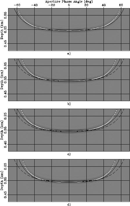
Figure
illustrates this fact by
showing a similar experiment as the one shown in
Figure ,
but with a perturbation 10 times larger;
that is, with
).
Figure
illustrates this fact by
showing a similar experiment as the one shown in
Figure ,
but with a perturbation 10 times larger;
that is, with ![]() .As in Figure ,
the four panels correspond to four rock types:
a) Isotropic, b) Taylor Sand, c) Mesa Clay Shale,
and
d) GreenLight River Shale,
and the lines superimposed onto the images are the RMO functions
computed by using
the correct values for
.As in Figure ,
the four panels correspond to four rock types:
a) Isotropic, b) Taylor Sand, c) Mesa Clay Shale,
and
d) GreenLight River Shale,
and the lines superimposed onto the images are the RMO functions
computed by using
the correct values for ![]() (solid lines),
and by using
(solid lines),
and by using ![]() in place of
in place of ![]() (dashed lines).
With large perturbations,
the predicted RMO functions differ from the actual RMO
functions at wide aperture angles
even when the correct values of the group angles are used
in equation 20.
However, even with such large perturbations
the predicted RMO functions are still useful approximations of the
actual RMO functions.
In particular, it can be observed that the
predicted RMO function correctly approximates the differences
in shape of the actual RMO function among the rock types.
These shape variations are related to the variations in shape of the wavefronts,
which are reflected in the predicted RMO function
through the variations in the mapping from phase angles to group angles.
(dashed lines).
With large perturbations,
the predicted RMO functions differ from the actual RMO
functions at wide aperture angles
even when the correct values of the group angles are used
in equation 20.
However, even with such large perturbations
the predicted RMO functions are still useful approximations of the
actual RMO functions.
In particular, it can be observed that the
predicted RMO function correctly approximates the differences
in shape of the actual RMO function among the rock types.
These shape variations are related to the variations in shape of the wavefronts,
which are reflected in the predicted RMO function
through the variations in the mapping from phase angles to group angles.
 |
 |
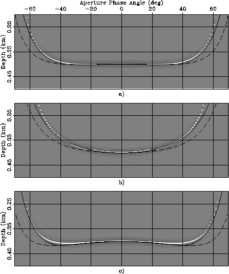
Figures and
show examples of the application of the generalized
RMO functions expressed
in equations 24-26.
As in
Figures -,
I show the ADCIGs for three different anisotropic rock types,
but, differently from the previous figures, not for the isotropic case.
The order of the rock types is the same as in
Figures -;
that is: panels a) correspond to Taylor Sand,
panels b) to Mesa Clay Shale, and
panels c) to GreenLight River Shale.
Furthermore, as in
Figures -,
one figure (Figure )
shows the ADCIG obtained with a smaller perturbation
than the ADCIGs shown in the other figure
(Figure ).
The ADCIGs shown in Figure
were obtained by performing isotropic migration
on the synthetic data modeled assuming anisotropic velocity.
The ADCIGs shown in Figure
were computed by scaling by .25 the parameter perturbations used
to compute Figure .
The lines superimposed onto the images are the RMO functions
computed by using
the correct values for ![]() (solid lines),
and by using
(solid lines),
and by using ![]() in place of
in place of ![]() (dashed lines).
(dashed lines).
The predicted RMO functions accurately track the actual RMO functions
when the parameter perturbations are sufficiently
small to be within the range of accuracy of the
linearization at the basis of the derivation of
equation 20 (Figure ).
But even when the perturbations are large
(Figure ) and
cause a substantial RMO (up to 30% of the reflector depth)
the predicted RMO functions are excellent approximations
of the actual RMO functions.
The RMO functions associated with the two strongly anelliptic rocks (Taylor Sand and GreenLight River Shale) exhibit a characteristic oscillatory behavior; the events at narrow-aperture angles are imaged deeper than the normal incidence event, whereas the events at wide-aperture angles are imaged shallower. This oscillatory behavior is well predicted by the analytical RMO function introduced in equations 24-26.
In contrast,
the approximation of the group angles with the phase angles
(dashed lines in the figures)
seriously deteriorates the accuracy of the predicted RMO functions.
Notice that, in contrast with the uniform-perturbation case
illustrated in
Figures - ,
the dashed lines are different among the panels,
because the derivatives
of the slowness function with respect to
the perturbation parameters depend on the anisotropic parameters
of the background medium.
 |
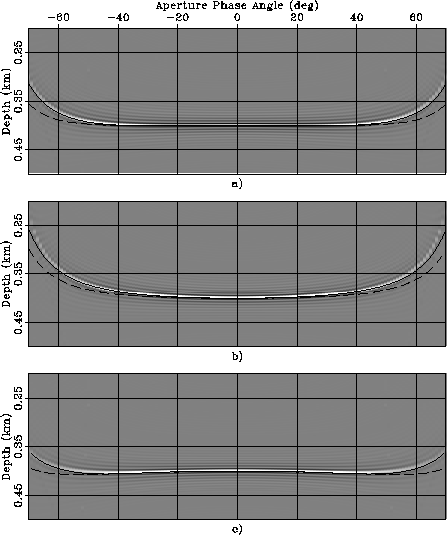 |
.
The anisotropic data were modeled assuming
three rock types:
a) Taylor Sand, b) Mesa Clay Shale,
and
c) GreenLight River Shale.
Superimposed onto the images are the RMO functions
computed using equation 20.
The solid line was computed when


