


The presence of focusing will be reported to the appropriate midpoint, not to the receiver location. This is done because the midpoint coordinate is orthogonal to the offset coordinate in the prestack data space.
The figures below feature straight rays which may seem to indicate constant velocity. However, this takes place only for ease of drawing; the reasoning that follows does not require constant velocity. I will also consider a single signed offset h. The mental experiments to be performed below will be identical both for any other offset and for the prestack dataset taken together.
Figures ![[*]](http://sepwww.stanford.edu/latex2html/cross_ref_motif.gif)
|
f1
Figure 1 Single offset seismic experiment - part 1: propagation from sources to reflector, and graph with focusing at the reflector | 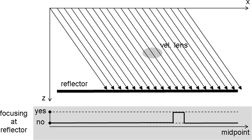 |

|
f2
Figure 2 Single offset seismic experiment - part 1: graph with focusing at the reflector (bottom), propagation from the reflector to the receivers, and graph with focusing as recorded by receivers (top) | 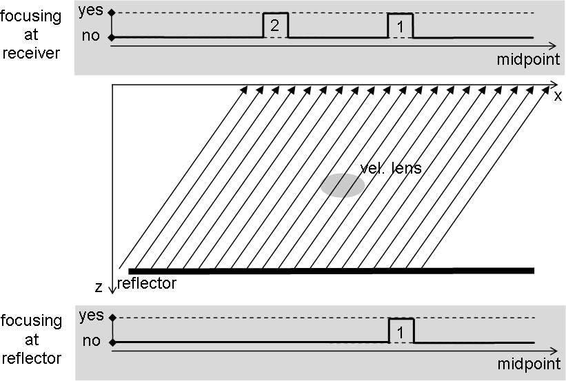 |
),
the wavefield propagates from the sources to the reflector. Only a
single midpoint local area is affected by focusing. In the second step
(Figure ), the wavefield propagates to the
surface. Already existing focusing is preserved, and a new pass
through the heterogeneity causes a second focusing area to appear. The
focusing areas detected by the receivers at the surface are reported
at the appropriate midpoints (not receiver locations) in the upper
graph. The two midpoint local areas in which focusing is present are
located at the intersection of the two arms of a midpoint-offset
``Kjartansson V'' Kjartansson (1979) with a line of constant offset h.
At this point one could make the argument that migration by definition recovers amplitudes at the reflector, and it cannot solve illumination problems, so effect 1 in Figure will not be removed by migration, and one should instead try a regularized inversion that will smooth out small irregularities. Let us however examine more closely what happens with the energy from that offset when we do shot-profile migration using all shots.
Downward continuation of the shots wavefields is properly
described by Figure and will produce at the reflector, as
expected, the same focusing as the real experiment. Downward
continuing the receivers (Figure
)
|
f3
Figure 3 Downward continuing the receivers in shot-profile migration: graph with focusing as recorded in the data (top), downward continuation with the correct velocity through the heterogeneity, and graph with residual focusing at the reflector (bottom) | 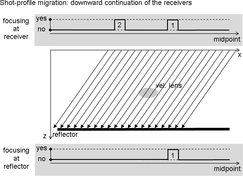 |
|
f4
Figure 4 The wavefields need only be similar, not uniform, in order for the imaging condition to produce a uniform-amplitude (no focusing) reflector. | 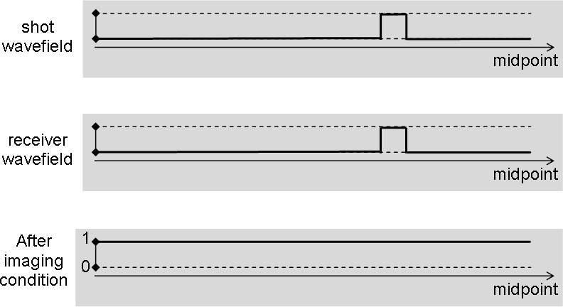 |
) the shot wavefield and the
receiver wavefield are identical in every point, and therefore the
uniform value of 1 for reflectivity is recovered. Shot-profile
migration with all sources therefore completely eliminates FEAVO from
the image if the correct velocity is provided. Survey-sinking
migration, being mathematically equivalent to it Biondi (2003),
also eliminates FEAVO if the velocity is provided.