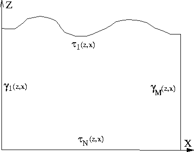
![[*]](http://sepwww.stanford.edu/latex2html/cross_ref_motif.gif) illustrates these concepts for the example
of 2D wave-equation migration from topography.
illustrates these concepts for the example
of 2D wave-equation migration from topography.
Generating orthogonal coordinate system meshes from PFs requires
ascribing a physical interpretation to equipotentials: they are
equivalent to extrapolation steps. Similarly, the characteristics of the
PF gradient field are intrinsically related to geometric coordinate system rays.
Figure ![[*]](http://sepwww.stanford.edu/latex2html/cross_ref_motif.gif) illustrates these concepts for the example
of 2D wave-equation migration from topography.
illustrates these concepts for the example
of 2D wave-equation migration from topography.
|
topocoord
Figure 1 Scenario of migration from topography. The upper and lower topographic surfaces are denoted |  |
This scenario requires extrapolating a wavefield comprised of M
traces into the subsurface a total of N steps, which ideally
occurs directly from the topographic surface.
The upper boundary of the computational domain, denoted
![]() in this figure, is the acquisition surface. The lower
boundary, denoted
in this figure, is the acquisition surface. The lower
boundary, denoted ![]() , is the desired flat subsurface datum.
These two bounding surfaces are connected by two curves,
, is the desired flat subsurface datum.
These two bounding surfaces are connected by two curves,
![]() and
and ![]() , extending between the first and
last extrapolation levels.
, extending between the first and
last extrapolation levels.
Solving for a PF satisfying Laplace's equation first requires specifying appropriate boundary conditions. Because distinct upper and lower equipotentials are desired, these two surfaces must have different constant values. Thus, I choose the following boundary conditions,
| |
(4) |
The Laplace's equation defined by the boundary conditions in Equation (4) is representable by a system of equations similar those commonly solved with conjugate gradient methods Claerbout (1999),
| |
(5) |
| (6) |
I use the following algorithm to obtain PF solution, ![]() :
: