

Next: Theory of noise attenuation
Up: Wilson and Guitton: Linear
Previous: Introduction
The complete teleseismic wavefield (Utotal) recorded at the surface can be represented as a linear combination of the impinging source wavefield (usrc), a specularly scattered wavefield (uspec), a diffracted wavefield (udiff), and an ambient noise wavefield (n) present at all times.
|  |
(1) |
Data+Model
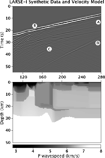
Figure 1 Synthetic seismograms (a) calculated from the LARSE-I velocity model Baher et al. (2004) (b) generated by a steeply dipping incident plane wave from the base of the model (approximation of actual teleseismic source-receiver geometry). The arrivals marked (A) represent specularly scattered arrivals from laterally coherent structures. Notice these arrivals follow a similar moveout to the direct arrivals. Diffractions from both the bottom of the basin (B) and Moho topography (C) show a clearly different moveout and are slightly less planar than the direct arrival. The side reflection related to the boundary conditions of the synthetic model, marked as (D), approximates source-side scattered phases that have similar moveout to the direct arrival, such as pP.

We assume either an isotropic character for the ambient noise (n) or that the highest amplitude components of the ambient noise wavefield (e.g. microseismic noise) do not follow the dominant moveout of teleseismic P wavefields. The speculary scattered portion of the wavefield contains plane wave arrivals generated at laterally continuous structures with little to no structural dip (arrivals marked A on Figure ![[*]](http://sepwww.stanford.edu/latex2html/cross_ref_motif.gif) ). The diffracted wavefield (arrivals marked B on Figure
). The diffracted wavefield (arrivals marked B on Figure ![[*]](http://sepwww.stanford.edu/latex2html/cross_ref_motif.gif) ) consists of non-planar arrivals generated by point scatterers and short wavelength structures (
) consists of non-planar arrivals generated by point scatterers and short wavelength structures ( 1/2 of the array aperture). For certain point scatterers, diffracted energy will arrive as plane waves that may appear as specularly scattered arrivals (arrivals marked C on Figure
 ![[*]](http://sepwww.stanford.edu/latex2html/cross_ref_motif.gif) ). In these instances, there will be no way to discriminate between a specularly scattered arrival from a planar,sub-horizontal interface and a diffraction except by comparing the scattered arrival slowness to that of the direct arrival.
). In these instances, there will be no way to discriminate between a specularly scattered arrival from a planar,sub-horizontal interface and a diffraction except by comparing the scattered arrival slowness to that of the direct arrival.
TeleGeometry
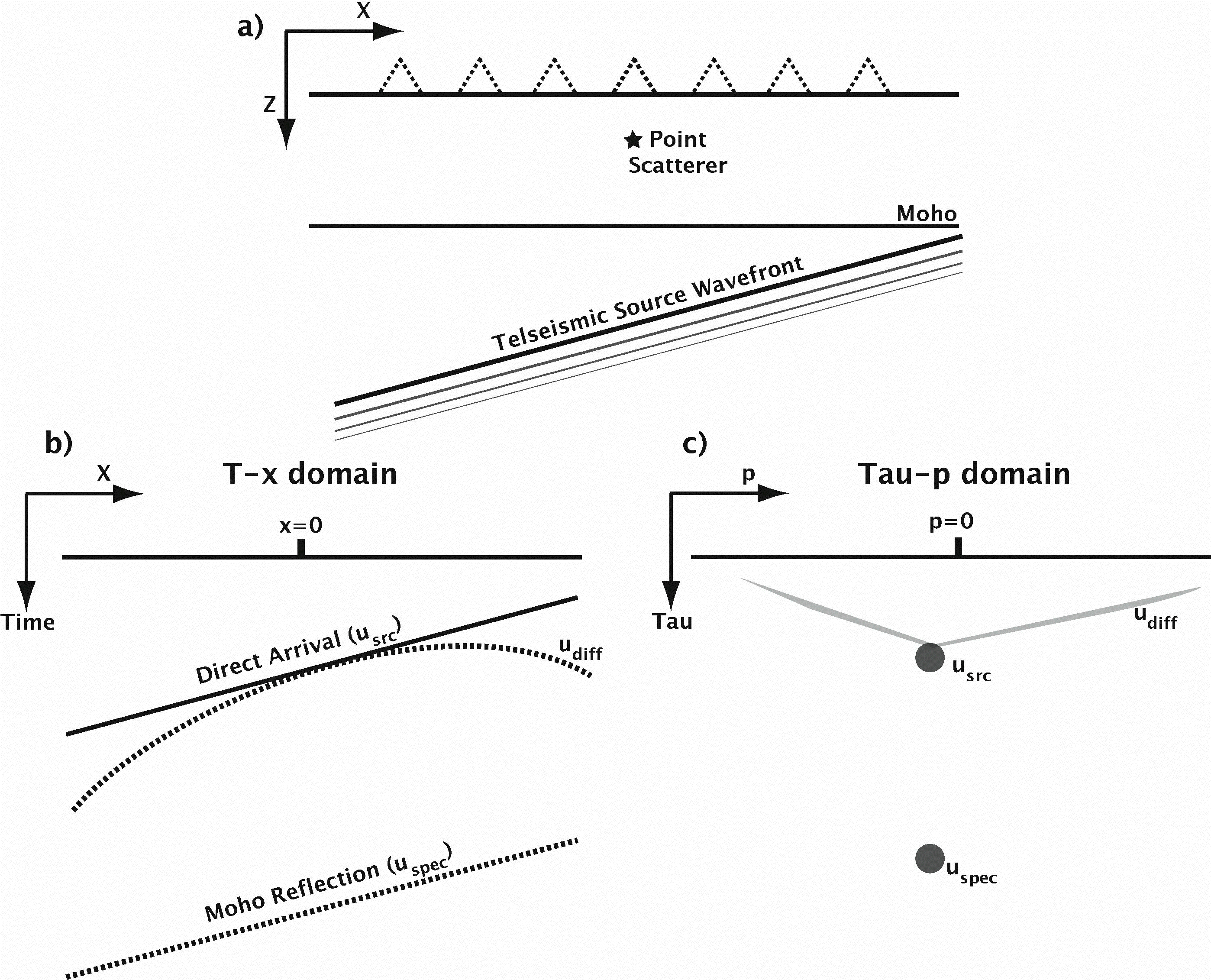
Figure 2 Figure showing representation of the teleseismic wavefield in the physical domain (a), the data domain (b), and the linear  -p domain (c). By applying the linear radon transform we can differentiate between speculalrly scattered and diffracted waves as shown in (c).


Next: Theory of noise attenuation
Up: Wilson and Guitton: Linear
Previous: Introduction
Stanford Exploration Project
5/3/2005

![[*]](http://sepwww.stanford.edu/latex2html/cross_ref_motif.gif) ). The diffracted wavefield (arrivals marked B on Figure
). The diffracted wavefield (arrivals marked B on Figure ![[*]](http://sepwww.stanford.edu/latex2html/cross_ref_motif.gif) ) consists of non-planar arrivals generated by point scatterers and short wavelength structures (
) consists of non-planar arrivals generated by point scatterers and short wavelength structures (![]() 1/2 of the array aperture). For certain point scatterers, diffracted energy will arrive as plane waves that may appear as specularly scattered arrivals (arrivals marked C on Figure
1/2 of the array aperture). For certain point scatterers, diffracted energy will arrive as plane waves that may appear as specularly scattered arrivals (arrivals marked C on Figure ![[*]](http://sepwww.stanford.edu/latex2html/cross_ref_motif.gif) ). In these instances, there will be no way to discriminate between a specularly scattered arrival from a planar,sub-horizontal interface and a diffraction except by comparing the scattered arrival slowness to that of the direct arrival.
). In these instances, there will be no way to discriminate between a specularly scattered arrival from a planar,sub-horizontal interface and a diffraction except by comparing the scattered arrival slowness to that of the direct arrival.
