

Next: Cascading image-construction operations
Up: Liner and Vlad: Multiple
Previous: Introduction
Let us assume that reflecting interface i is given through two
points belonging to it, A and B. Since traveltimes are
computed independently for each CMP, we use a coordinate system
with the origin in the midpoint between source and receiver (both located at
the surface). In this CMP-centric coordinate system, interface i can
be expressed as
|  |
(1) |
where  is the dip of the interface:
|  |
(2) |
and di is the distance from the CMP point to the
interface:
|  |
(3) |
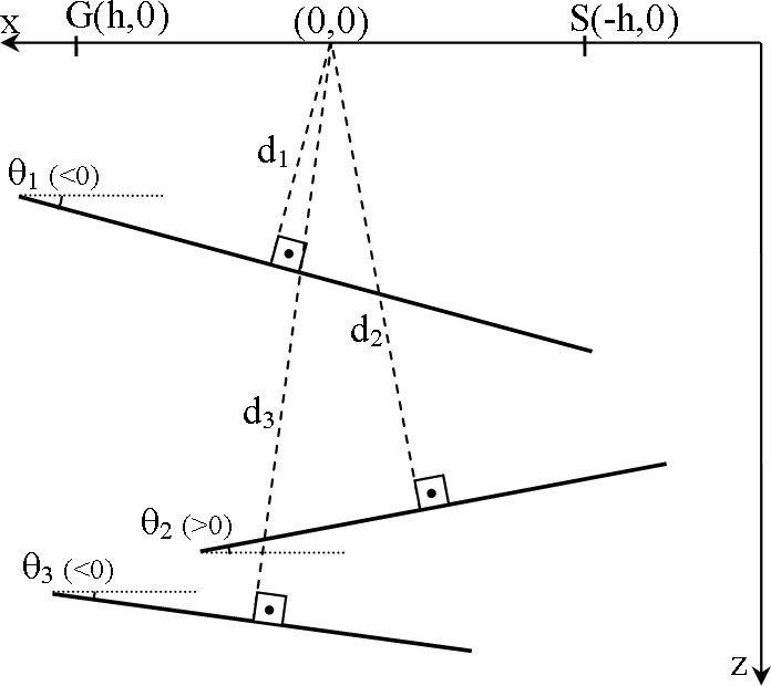
Figure ![[*]](http://sepwww.stanford.edu/latex2html/cross_ref_motif.gif) shows a three-interface example.
shows a three-interface example.
peglegmodel
Figure 1 Three interface reflectivity model
for illustrating the meaning of the notations di and  . Notice the sign convention for angles. . Notice the sign convention for angles.
|
|  |

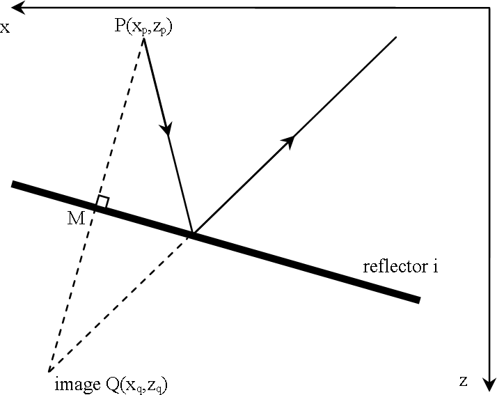
Similar to Levin and Shah (1977), we use the method of images to compute
traveltimes. Let us denote with  the image of
point
  through reflector
i (see Figure
 ![[*]](http://sepwww.stanford.edu/latex2html/cross_ref_motif.gif) ). Through simple analytical geometry we find that
). Through simple analytical geometry we find that
| ![\begin{displaymath}
\underbrace {\left[ {\begin{array}
{*{20}c}
{x_q } \\ {z_q...
...a_i } \\ \end{array}} \right]}_{{\bf b}\left(\theta_i\right) }.\end{displaymath}](img7.gif) |
(4) |
imex
Figure 2 Image point concept
illustration.
|
|  |


Next: Cascading image-construction operations
Up: Liner and Vlad: Multiple
Previous: Introduction
Stanford Exploration Project
10/23/2004
![[*]](http://sepwww.stanford.edu/latex2html/cross_ref_motif.gif) shows a three-interface example.
shows a three-interface example.

![]() the image of
point
the image of
point ![]() through reflector
i (see Figure
through reflector
i (see Figure ![[*]](http://sepwww.stanford.edu/latex2html/cross_ref_motif.gif) ). Through simple analytical geometry we find that
). Through simple analytical geometry we find that
![\begin{displaymath}
\underbrace {\left[ {\begin{array}
{*{20}c}
{x_q } \\ {z_q...
...a_i } \\ \end{array}} \right]}_{{\bf b}\left(\theta_i\right) }.\end{displaymath}](img7.gif)
