


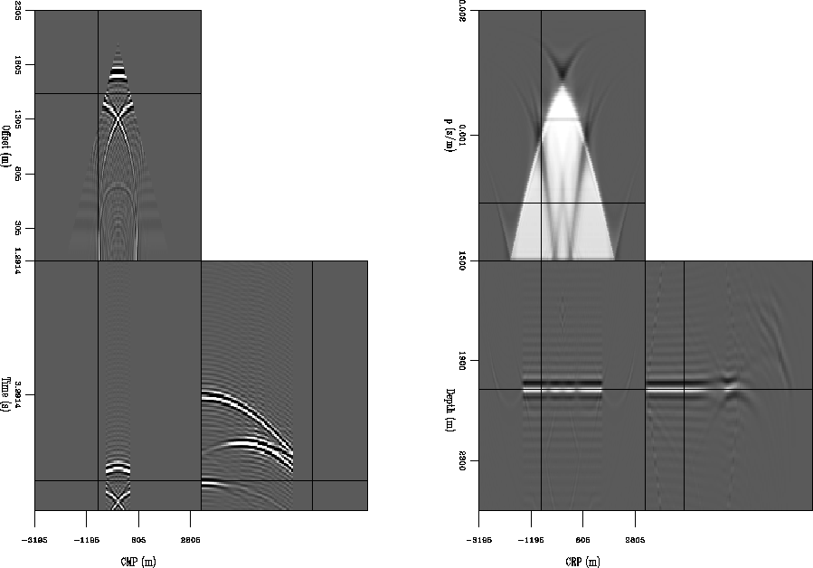
In a perfect world, we would have perfect data and the data fitting goal would allow us to construct a perfect model of the subsurface without needing any regularization. However, we never have perfect data. It is always corrupted by noise and the acquisition geometry is always a compromise between cost and what would provide sufficient data to image the subsurface. The latter is a particularly bad problem in areas of complex subsurface. Subsurface volumes with high velocity contrasts, such as salt bodies or even the simple low velocity lens model seen in Figure 1, are difficult to image at least partially due to seismic energy being directed outside of the limited survey area. The rays in Figure 1 show how seismic energy that is reflected at the flat reflector is affected by the low velocity lens. The maximum offset used in this paper is 4000 m, so the energy that is redirected by the lens will not be recorded. If we look at the synthetic data generated for this model (left panel of Figure 2), we can see the bounds of the survey cutting off the recorded events. The energy that leaves the survey bounds causes the migration result (right panel of Figure 2) to have holes in the common image gathers (CIGs).
Figure 2 indicates that we need to reconsider our
fitting goals. Our model is incomplete because we are missing data.
If we include the data that leaves the survey (![]() ), our fitting
goals become:
), our fitting
goals become:
Initially, ![]() is set to zero, since by definition we haven't
recorded it. However, as we perform conjugate-gradient iterations
of the fitting goals, regularizing the model with each iteration, we are
filling in the parts of the model that correspond to
is set to zero, since by definition we haven't
recorded it. However, as we perform conjugate-gradient iterations
of the fitting goals, regularizing the model with each iteration, we are
filling in the parts of the model that correspond to ![]() and
thereby reconstructing some version of
and
thereby reconstructing some version of ![]() .
.
In practice, RIP includes ![]() by padding the original data space
with zero traces. However, since we are doing conjugate-gradient
iterations, it is important
to mask out the padded traces during each iteration. Otherwise the
``recovered''
by padding the original data space
with zero traces. However, since we are doing conjugate-gradient
iterations, it is important
to mask out the padded traces during each iteration. Otherwise the
``recovered'' ![]() would exist in the data residual space and
confuse the minimization. Defining
would exist in the data residual space and
confuse the minimization. Defining
| (4) |
and including the weighting operator ![]() , the fitting goals become:
, the fitting goals become:
| |
(5) | |
|
symesray
Figure 1 Velocity model with a flat reflector under a low velocity lens. The maximum offset used for this experiment is 4000 m, so some of the rays representing seismic energy are directed outside of the survey bounds. Synthetic provided by Bill Symes and The Rice Inversion Project. | 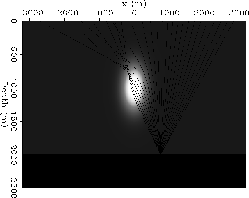 |


 |