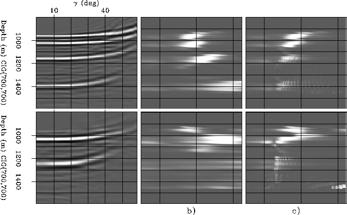
Migrating with an incorrect velocity results in gathers frowning downward if the velocity is too high, and gathers smiling upward if the velocity is too slow. Biondi et al. (2003) analyze the kinematics of ADCIGs. Assuming stationary-raypath, or straight rays, the authors show that the apparent image point in the angle domain is located on the normal to the apparent reflector, and provide a 2-D RMO function to quantify the amount of the shift of the image point:
| |
(1) |
|
stk_2D_700_450
Figure 4 Velocity error analysis by semblance using a 2-D RMO function on CIG700 on the top row, and on CIG425 on the bottom row. a) Stack over |  |
In the case of a flat reflector (![]() ), equation
(1) reduces to
), equation
(1) reduces to
| |
(2) |
Both functions are tested on two CIGs of the model displayed in Figure
1.
Figure 4 illustrates a velocity error
analysis by semblance.
The top row is CIG700, and the bottom row is CIG425.
The dips for CIG700 range from 0 to 45.The dips for CIG700 range from 45 to 60.Figure 4a is the stack over ![]() for the two CIGs.
The upward smiles indicate that the migration velocity is too low.
The velocity error being
for the two CIGs.
The upward smiles indicate that the migration velocity is too low.
The velocity error being ![]() , the peak of semblance will ideally
be centered at
, the peak of semblance will ideally
be centered at ![]() .
.
Figure 4b is the velocity error spectrum of the
left panels in the absence of dip information and using
![]() (equation (2)).
As expected, the peak of semblance is correctly positioned for
the flat reflector at depth 960 m.
However, the other peaks of semblance are mispositioned for the
steeper reflectors, where the zero-dip assumption is not
valid. For the steepest reflector, the peak of semblance is
out of the semblance panel.
(equation (2)).
As expected, the peak of semblance is correctly positioned for
the flat reflector at depth 960 m.
However, the other peaks of semblance are mispositioned for the
steeper reflectors, where the zero-dip assumption is not
valid. For the steepest reflector, the peak of semblance is
out of the semblance panel.
Figure 4c is the velocity error spectrum of
the left panel, using the RMO function with the knowledge of the dip
(equation (1)).
The dip does not have to be known a priori; it can be extracted
from the migrated cube between the migration step and the
velocity error estimation step.
The peaks of semblance are better focused but are still not
accurate enough, especially for the steepest reflector, on
which we read ![]() , signifying that the velocity is
correct. To correct this, we need to take into account 3-D
events.
, signifying that the velocity is
correct. To correct this, we need to take into account 3-D
events.
The 2-D RMO functions can be used to extract the velocity error from the gathers of the migrated cube. The simple RMO function works for flat reflectors. When the dip information in included, the RMO function corrects the error generated by steeply dipping reflectors. However, the peaks are not correctly positioned because of 3-D events that are not appropriately processed by equation (1).