|
Flow
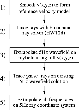
Figure 1 Methodology flow chart illustrating the five processing steps involved in calculating an updated ray-coordinate system in our approach. |  |
Calculating an updated coordinate system using phase-ray tracing is a fairly simple procedure involving five processing steps. The goal of this processing is the formation of a coordinate system that better conforms to the orientation of propagating wavefronts. A flow chart of a typical processing sequence is presented in Figure 1.
|
Flow
Figure 1 Methodology flow chart illustrating the five processing steps involved in calculating an updated ray-coordinate system in our approach. |  |
The first step involves developing a velocity model with adequate smoothness such that the corresponding rayfield is triplication-free. To do this, we apply stationary triangular smoothing operators to the true velocity model. The second step is the generation of an initial rayfield using the prepared velocity model. Point source rayfields are modeled by specifying a set of initial ray points located on an arc of some small radius about the shot point. Plane-wave rayfields are generated by seeding rays at all areal acquisition points, and shooting at a constant angle. Planar ray-coordinate systems at different shooting angles are used for extrapolating plane-waves of similar dip. Generally, steps 1 and 2 are repeated until a triplication-free ray-coordinate system is produced.
The third step is to generate an initial monochromatic wavefield solution by: i) performing RWE on the calculated smooth rayfield; and ii) interpolating the resulting wavefield to a Cartesian basis. This step requires mapping a velocity model to the initial ray-coordinate system. Importantly, we are free to choose a velocity function that is not identical to the true model. One strategy is to choose a velocity model that is somewhat rougher than that used to calculate an initial rayfield, but smoother than the exact model. A judicious model choice may yield a wavefield that triplicates, but it should not be too complex to inhibit phase-ray computation.
The fourth step involves using the initial wavefield's phase gradient to calculate an updated ray-coordinate system. This procedure is identical to the calculation of phase-rays discussed in Shragge and Biondi (2003). Attention need be paid to locations where the wavefield magnitude is zero, as they lead to unstable phase-ray calculation. However, because the rayfield only serves as a proxy for the true wavefront extrapolation direction, we may freely regularize it through application of triangular smoothing operators to generate a smooth ray-coordinate system.
The final step in the procedure comprises: i) a RWE of the broadband wavefield on the updated ray-coordinate system using the true velocity model; ii) and interpolating the resulting wavefield to a Cartesian basis. In principle, steps three and four may be repeated incorporating velocity models of increasing roughness that tend to true velocity model; however, we do not apply this extension here.