Next: Discussion
Up: Alvarez et al.: Diffracted
Previous: A look at the
With ideal data, attenuating both specularly-reflected and diffracted
multiples could, in principle, be accomplished simply by zeroing out
(with a suitable taper) all the q-planes
except the one corresponding to q=0 in the model cube m(z',q,h)
and taking the inverse apex-shifted Radon transform.
In practice, however, the primaries may not be well-corrected
and primary energy may map to a few other q-planes. Energy from
the multiples may also map to those planes and so we have the usual
trade-off of primary preservation versus multiple attenuation. The
advantage now is that the diffracted multiples are well focused to
their corresponding h-planes and can therefore be easily attenuated.
Rather than suppressing the multiples in the model domain, we chose to suppress
the primaries and inverse transform the multiples to the data space.
The primaries were then recovered by subtracting the multiples from the data.
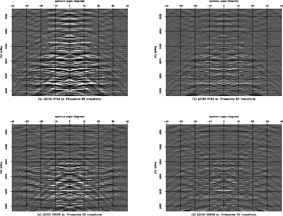
Figure 5 shows a close-up comparison of the primaries extracted
with the standard 2D transform (Sava and Guitton, 2003) and with the
apex-shifted Radon transform for the two ADCIGs at the top in Figure 2.
The standard transform (Figures 5a and 5c)
was effective in attenuating the specularly-reflected multiples, but failed
at attenuating the diffracted multiples (below 4000 m), which are left as residual
multiple energy in the primary data. Again, this is a
consequence of the apex shift of these multiples. There appears not to be
any subsalt primary in Figures 5a and 5b
and only one clearly visible subsalt primary in Figures 5c
and 5d (just above 4400 m). This primary was well
preserved with both transformations.
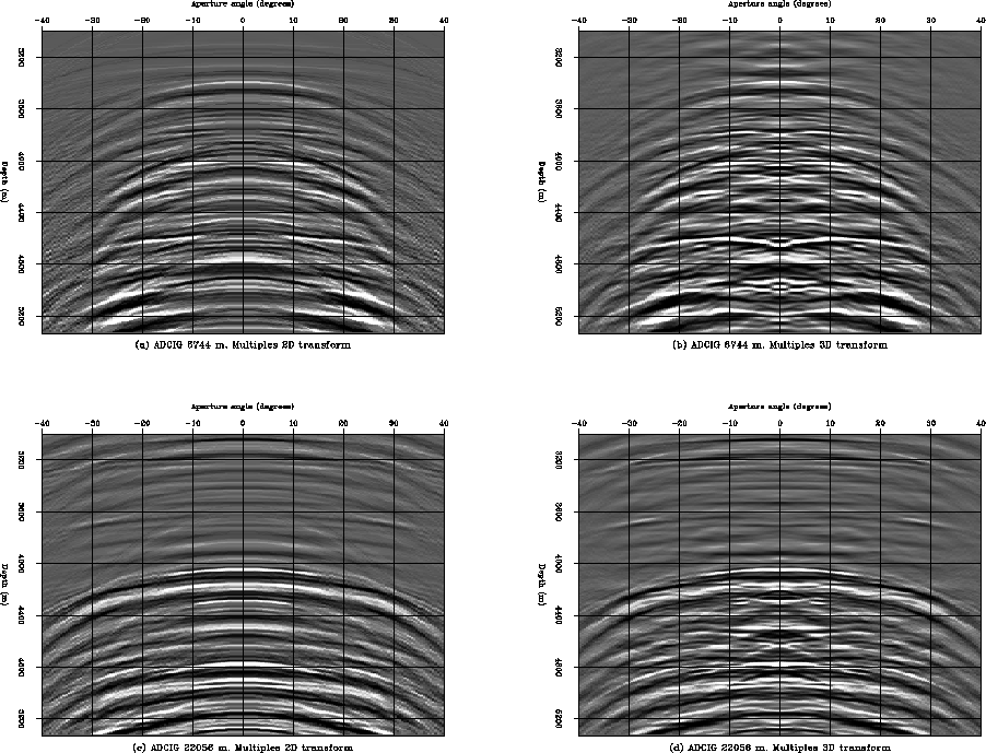
Figure 6 shows a similar comparison for the extracted multiples.
Notice how the diffracted multiples were correctly identified and extracted
by the 3D Radon transform, in particular in Figure 6b. In
contrast, the standard 2D transform misrepresent the diffracted multiples
as though they are specularly-reflected multiples as seen in
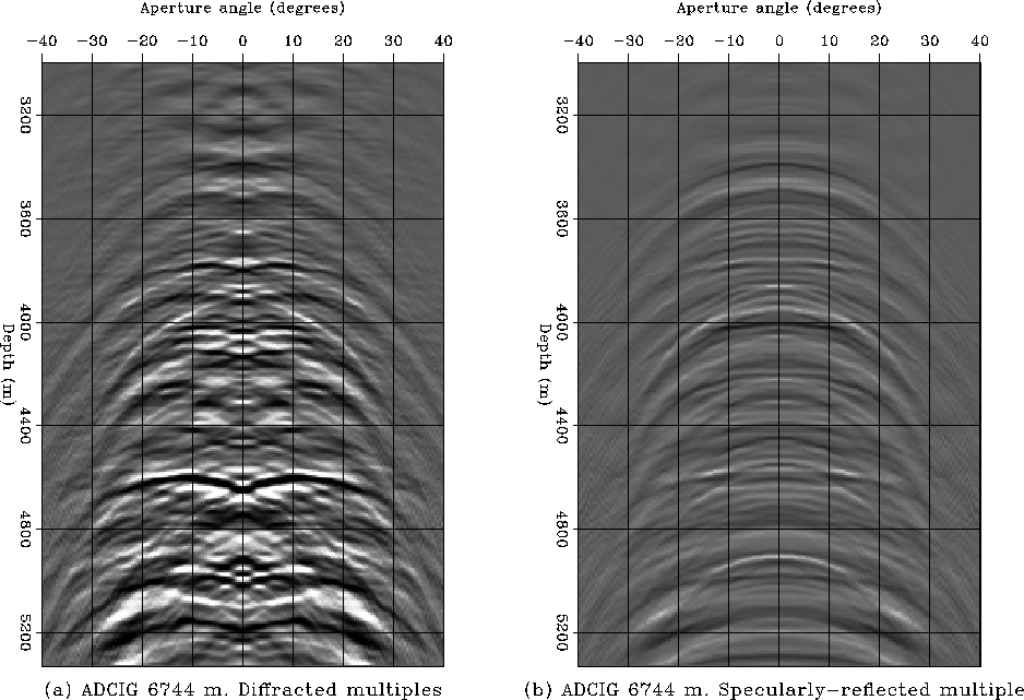
Figure 6a. We can take advantage of the 3D model representation
to separate the diffracted multiples from the specularly-reflected ones. This
is shown in Figure 7. The diffracted multiples are
clearly seen in Figure 7c.
comp_prim1
Figure 5 Comparison of primaries extracted with
the 2D Radon transform (a) and (c) and with the apex-shifted Radon transform (b)
and (d). Notice that some of the diffracted multiples remain in the result with
the 2D transform.
 comp_mult1
Figure 6 Comparison of multiples extracted
with the 2D Radon transform (a) and (c) and with the apex-shifted Radon transform (b)
and (d).
comp_mult2
Figure 7 Comparison of (a) diffracted
and (b) specularly-reflected multiples for the ADCIG in Figure 2a.
Notice the lateral shifts in the apexes of the diffracted multiples.
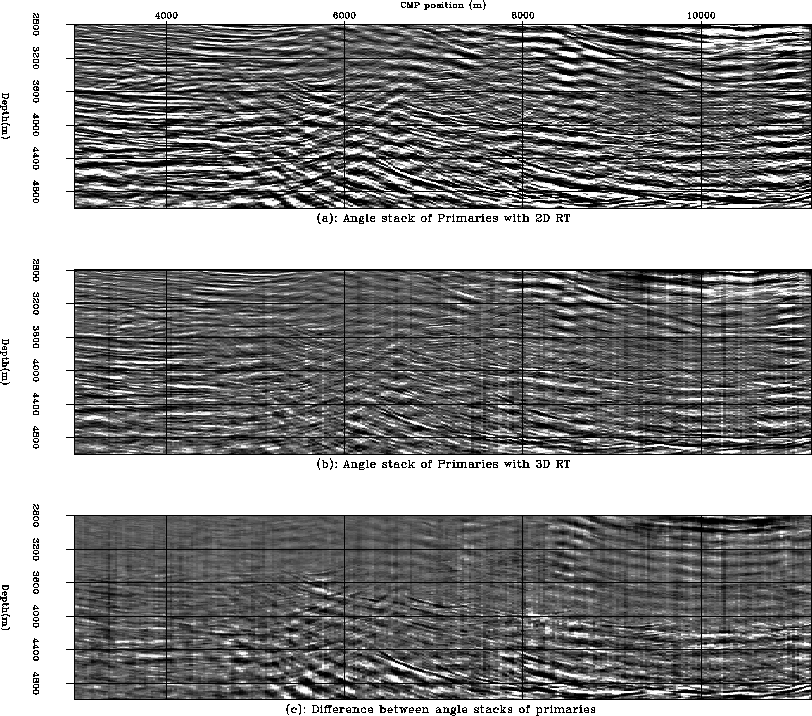
In order to assess the effect of better attenuating the diffracted multiples on
the angle stack of the ADCIGs we processed a total of 310 ADCIGs corresponding
to horizontal positions 3000 m to 11000 m in Figure 1.
Figure 8 shows a close-up view of the stack of the
primaries extracted with the 2D Radon transform, the stack of the primaries
extracted with the 3D Radon transform and their difference.
Notice that the diffracted multiple energy below the edge of the salt (5000 m to
7000 m) that appears as highly dipping events with the 2D transform, has been
attenuated with the 3D transform. This is shown in detail in
Figure 8c. It is very difficult to identify any primary
reflections below the edge of the salt, so
it is hard to assess if the primaries have been equally preserved with both methods.
It is known, however, that for this dataset, there are no multiples above a depth of
about 3600 m, between CMP positions 3000 m to 5000 m. The fact that the difference
panel appears nearly white in that zone shows that the attenuation of the
diffracted multiples did not affect the primaries. Of course, this is only true
for those primaries that were correctly imaged, so that their moveout in the
ADCIGs was nearly flat. Weak subsalt primaries may not have been well-imaged
due to inaccuracies in the migration velocity field and may therefore have been
attenuated with both the 2D and the 3D Radon transform.
comp_prim1_stack
Figure 8 Comparison of angle stacks for
primaries.
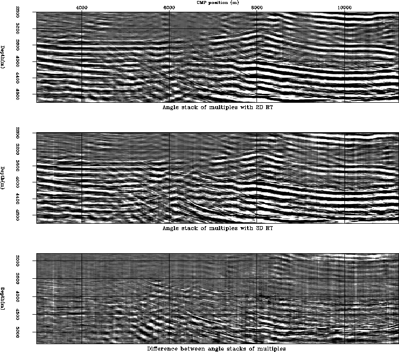
For the sake of completeness, Figure 9 shows the extracted
multiples with the 2D and the 3D Radon transform and their difference. Again,
the main difference is largely in the diffracted multiples.
comp_mult1_stack
Figure 9 Comparison of angle stacks for
multiples.
Next: Discussion
Up: Alvarez et al.: Diffracted
Previous: A look at the
Stanford Exploration Project
5/23/2004