

Next: Wavefield extrapolation in phase-ray
Up: Shragge and Biondi: Phase-rays
Previous: Phase-ray formulation
Examples of traced phase-rays are presented in this section using
a salt body velocity field as a didactic model.
The background velocity of the model, shown in figure
![[*]](http://sepwww.stanford.edu/latex2html/cross_ref_motif.gif) e, is a typical Gulf of Mexico v(z) velocity gradient.
The superposed salt body is characterized by higher wave speeds (4700 m/s) and a
fairly rugose bottom of salt interface.
G5paper
e, is a typical Gulf of Mexico v(z) velocity gradient.
The superposed salt body is characterized by higher wave speeds (4700 m/s) and a
fairly rugose bottom of salt interface.
G5paper
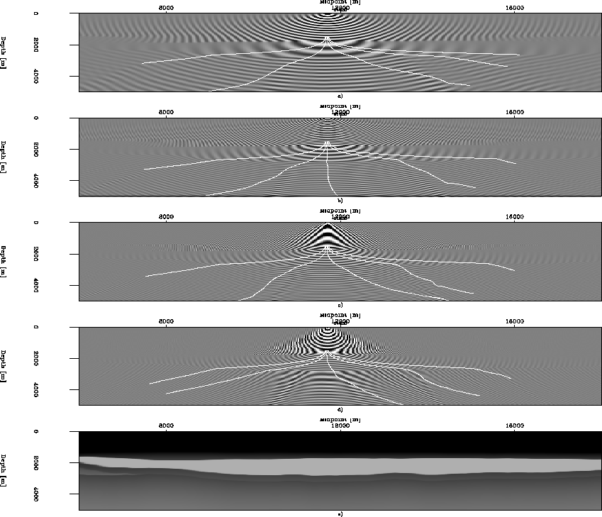
Figure 2 Five phase-rays traced through
monochromatic wavefields. Wavefields were generated by a split-step Fourier
operator in Cartesian coordinates for a shot point at 11700 m
using the velocity model illustrated in e). a) 5
Hz wavefield; b) 10 Hz wavefield; c) 15 Hz wavefield; d) 20 Hz
wavefield; and e) smoothed salt body model velocity field.


Figure ![[*]](http://sepwww.stanford.edu/latex2html/cross_ref_motif.gif) presents five phase-rays computed from
four different monochromatic wavefields.
The wavefields were generated for a shot point
located at 11700 m using a split-step Fourier operator
Stoffa et al. (1990) in a Cartesian coordinate system.
Each ray begins at the same point in all panels.
The rays to the extreme left and right in each panel show little
variability in their spatial location;
however, the three remaining rays are attracted to regions of
greater wavefield amplitude and their spatial locations vary with a
range up to 2000 m.
Accordingly, because rays originate at the same spot, observed
phase-ray movement is caused by changes in wavefield solution
and indicates frequency-dependent behavior.
presents five phase-rays computed from
four different monochromatic wavefields.
The wavefields were generated for a shot point
located at 11700 m using a split-step Fourier operator
Stoffa et al. (1990) in a Cartesian coordinate system.
Each ray begins at the same point in all panels.
The rays to the extreme left and right in each panel show little
variability in their spatial location;
however, the three remaining rays are attracted to regions of
greater wavefield amplitude and their spatial locations vary with a
range up to 2000 m.
Accordingly, because rays originate at the same spot, observed
phase-ray movement is caused by changes in wavefield solution
and indicates frequency-dependent behavior.
Phase-rays computed according to equations (9) may be
traced in reverse, from observation to source point, by using a
negative step interval.
Figure ![[*]](http://sepwww.stanford.edu/latex2html/cross_ref_motif.gif) illustrates this situation with the same
model as in figure
illustrates this situation with the same
model as in figure ![[*]](http://sepwww.stanford.edu/latex2html/cross_ref_motif.gif) .
.
G5backpaper
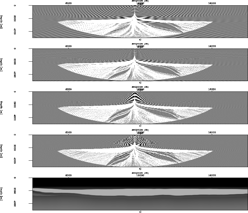
Figure 3 200 phase-rays traced
backwards through
monochromatic wavefields for velocity model shown in e). Initial ray
locations are points at regular intervals on a semicircular arc of
radius 5000 m. a) 5 Hz wavefield; b) 10 Hz wavefield; c) 15 Hz
wavefield; d) 20 Hz wavefield; and e) smoothed salt body model
velocity field.


Initial ray locations are points at regular intervals on a
semicircular arc of radius 5000 m.
Calculated phase-rays do not overlap and the ray-field is caustic-free.
Phase-ray density, though, is frequency-dependent, with significant
coverage gaps of variable size appearing in all four panels.
This suggests that an additional condition is required to ensure
that, when needed, ray density is more uniform.
One solution is to shoot a new ray between two successive rays
wherever intra-ray distance exceeds some threshold value.
In summary, these results illustrate a number of advantageous
characteristics of phase-rays: i) phase-ray ray-fields are
triplication-free; ii) ray tracing from areas of low wavefield
amplitude (e.g. shadow zones) to the source point is possible; and
iii) sufficient phase-ray density may be ensured by an additional
shooting of phase-rays wherever intra-ray spacing is too large.
These three traits provide the main impetus for using phase-ray
coordinates as a generalized coordinate system for wavefield
extrapolation Sava and Fomel (2003).


Next: Wavefield extrapolation in phase-ray
Up: Shragge and Biondi: Phase-rays
Previous: Phase-ray formulation
Stanford Exploration Project
10/14/2003

![[*]](http://sepwww.stanford.edu/latex2html/cross_ref_motif.gif) e, is a typical Gulf of Mexico v(z) velocity gradient.
The superposed salt body is characterized by higher wave speeds (4700 m/s) and a
fairly rugose bottom of salt interface.
e, is a typical Gulf of Mexico v(z) velocity gradient.
The superposed salt body is characterized by higher wave speeds (4700 m/s) and a
fairly rugose bottom of salt interface.
