Next: Frequency Domain
Up: Time-variant Filtering
Previous: Time-variant Filtering
The algorithm in the time-domain is:
- 1.
- Design the filters in the frequency domain. These may be trapezoidal
tapered filters
or some other suitable bandpass filter. We can consider these filters as
making up a matrix whose horizontal coordinate is time
 (that is, the
sample time of application of every filter) and whose vertical component is
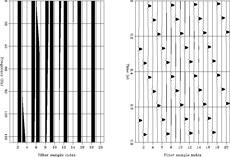
frequency as shown in the left-hand side of Figure 1.
(that is, the
sample time of application of every filter) and whose vertical component is
frequency as shown in the left-hand side of Figure 1.
- 2.
- Get the filter impulse responses in time domain. This essentially means
taking an inverse Fourier transform of each column of the left
panel in Figure 1.
- 3.
- Form the non-stationary impulse response matrix in time domain.
The right panel in Figure 1 shows an example of this matrix for
the case of three
different filters to be applied in three windows of data. The wavelet is zero
phase and the impulse responses are shifted so that the wavelet is centered
along the diagonal.
- 4.
- Apply the non-stationary convolution. This is done by matrix
multiplication
between the matrix in the right panel of Figure 1 and the
seismic trace to be filtered.
tvf_td1
Figure 1 Filter design in the time-frequency domain.
On the left, filter spectra as a function of time. On the right, impulse
responses on time


 tvf_fd1
Figure 2 Frequency domain convolutional matrix.
On the left, the filter spectra (amplitude only). The center ``trace'' represents
the stationary response, the traces
to the right positive frequencies and the traces to the left negative
frequencies (only a few ``traces'' are shown). On the right the complete
matrix shifted so that the stationary ``trace'' is on the diagonal of the
matrix
Next: Frequency Domain
Up: Time-variant Filtering
Previous: Time-variant Filtering
Stanford Exploration Project
6/8/2002