|
Slow-prism-ann
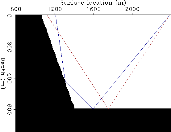
Figure 17 Velocity model assumed to create the synthetic data set. Superimposed onto the velocity is an example of prismatic-reflection ray path (solid line). |  |
To test the possibility of using reverse time migration to image prismatic reflection I created another synthetic data set. Figure 17 shows the velocity model used for generating the synthetic. The solid line superimposed onto the velocity is an example of prismatic-reflection ray path. I modeled and migrated 250 shots spaced 6.25 m apart, starting from the surface coordinate of 1,375 m. The receivers were in a symmetric split-spread configuration with maximum offset of 6,400 m.
To better analyze the behavior of reverse time migration in imaging prismatic reflections, I removed the primary reflections from the data. To achieve this goal I subtracted two other data sets from the data modeled assuming the velocity model shown in Figure 17. One of the data sets included the primary reflections from the flat reflector, and the other one the primaries from the dipping reflector. The two velocity models used to generate the primaries were created by breaking the black area shown in Figure 17 into two pieces, divided by a vertical line passing through the location of the corner (1.4 km).
To image prismatic reflections, the background velocity function needs to include at least one of the interfaces that generated the reflections. I assumed that the flat reflector was known, and thus I included a flat velocity interface at 600 m depth in the migration velocity model.
|
Slow-prism-ann
Figure 17 Velocity model assumed to create the synthetic data set. Superimposed onto the velocity is an example of prismatic-reflection ray path (solid line). |  |
Figure 18 is the image obtained migrating all the 250 shots. As expected by simple analysis of the raypaths, the prismatic reflections illuminate the dipping reflector more strongly in the deeper part than in the shallower part. The image shows also a high energy flat event on the right side of the corner, that is not a proper image of a reflection. In theory, such event should not be there. The primaries associated with the flat reflector were removed from the data. The prismatic reflections bouncing off the dipping layer are not imaged because the dipping layer is not present in the migration velocity. This artifact is likely to be caused by the (imperfect) correlation of the prismatic reflection (solid line in Figure 17) with reflections generated by the horizontal discontinuity in the migration velocity model (dashed line in Figure 17). This interpretation is corroborated by the presence of a faint low-frequency noise extending upward from the flat reflector.
Figure 19 shows on the left the offset-domain CIG (a) and on the right the angle-domain CIG (b). The CIGs are located at a surface location where prismatic reflections illuminate the dipping reflector (1,350 m). The energy focuses at zero offset, but the angle-domain CIG is not flat. This lack of flatness is likely to be caused by the fact that the source and receiver wavefields meet at the reflector when propagating along opposite vertical direction. I speculate that better angle-domain CIGs could be generated if I applied the generalized imaging condition expressed in equation (3), that includes the vertical subsurface offset.
|
Shot-Image-prism
Figure 18 Image of the synthetic data set containing the overturned reflections migrated with the correct velocity and at |  |
|
Shot-Cig-Ang-prism
Figure 19 Offset-domain CIG (left) and angle-domain CIG (right) corresponding to the image in Figure 18. Notice that the energy focuses at zero offset, but that the angle-domain CIG is not flat. This lack of flatness is likely to be caused by the fact that the source and receiver wavefields meet at the reflector when propagating along opposite vertical direction. |  |