

Next: Application to true-amplitude migration
Up: Compensating for irregular shot
Previous: Compensating for irregular shot
As described above, normalization by shot illumination only
approximates an inverse operation if the illumination problems come
from poor sampling on the shot axis (or reciprocal shot) rather than
on both shot and receiver axes.
As a best case scenario, to test the validity of this approach, I
generated a dataset consisting of 20 split-spread shots over the
Marmousi velocity model, using a paraxial Fourier finite-difference
wavefield extrapolation algorithm Ristow and Ruhl (1994). The receiver axis
was well sampled, as each shot-gather contained 200 traces.
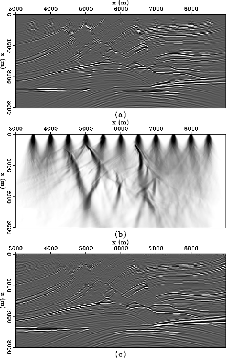
The top panel in Figure ![[*]](http://sepwww.stanford.edu/latex2html/cross_ref_motif.gif) shows the result of
migrating the 20 shots with the correct velocity model, and the center
panel shows the shot illumination.
Clearly areas of high illumination correspond to bright spots in the
migrated image. Panel (c) shows the migrated image
after normalization by the shot illumination. Although only 20 shots
were migrated into this image, its clarity is comparable with the full
migration of the entire dataset (about 240 shots).
It is also encouraging that while the shot locations are visible on
Figure
shows the result of
migrating the 20 shots with the correct velocity model, and the center
panel shows the shot illumination.
Clearly areas of high illumination correspond to bright spots in the
migrated image. Panel (c) shows the migrated image
after normalization by the shot illumination. Although only 20 shots
were migrated into this image, its clarity is comparable with the full
migration of the entire dataset (about 240 shots).
It is also encouraging that while the shot locations are visible on
Figure ![[*]](http://sepwww.stanford.edu/latex2html/cross_ref_motif.gif) (a), they are hidden in
Figure
(a), they are hidden in
Figure ![[*]](http://sepwww.stanford.edu/latex2html/cross_ref_motif.gif) (c): the normalized image appears to be
unbiased by the recording geometry.
(c): the normalized image appears to be
unbiased by the recording geometry.
marmsparseill1
Figure 7 Normalization by shot illumination:
the panel (a) shows shot profile migration with the correct
velocity model of 20 split-spread shots over the Marmousi model,
panel (b) shows shot illumination, and panel (c) shows the normalized
image.
![[*]](http://sepwww.stanford.edu/latex2html/movie.gif)


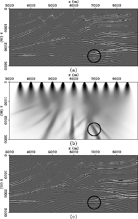
Compensation for shot illumination in Figure ![[*]](http://sepwww.stanford.edu/latex2html/cross_ref_motif.gif) worked so well partly because the modeling and migration procedures
were true adjoints. To test how robust this
normalization would be in the more realistic situation where the
modeling and migration procedures are not true adjoints, I migrated
the same 20 shots with an incorrect velocity model.
Panels (a) and (b) of Figure
worked so well partly because the modeling and migration procedures
were true adjoints. To test how robust this
normalization would be in the more realistic situation where the
modeling and migration procedures are not true adjoints, I migrated
the same 20 shots with an incorrect velocity model.
Panels (a) and (b) of Figure ![[*]](http://sepwww.stanford.edu/latex2html/cross_ref_motif.gif) show the
migrated image, and the corresponding shot illumination respectively.
Panel (c) shows the migrated image after normalization. Despite the
incorrect velocity, the amplitude artifact visible in
Figure
show the
migrated image, and the corresponding shot illumination respectively.
Panel (c) shows the migrated image after normalization. Despite the
incorrect velocity, the amplitude artifact visible in
Figure ![[*]](http://sepwww.stanford.edu/latex2html/cross_ref_motif.gif) (a) are largely gone from
Figure
(a) are largely gone from
Figure ![[*]](http://sepwww.stanford.edu/latex2html/cross_ref_motif.gif) (c). For example in the top 500 m of
the section, the footprint of the acquisition geometry is removed from
Figure
(c). For example in the top 500 m of
the section, the footprint of the acquisition geometry is removed from
Figure ![[*]](http://sepwww.stanford.edu/latex2html/cross_ref_motif.gif) (c). The vertical amplitude streaks
lower in the section are also reduced -- illumination of the target
reflectors at 2600 m depth is more uniform after normalization,
especially in the highlighted area.
(c). The vertical amplitude streaks
lower in the section are also reduced -- illumination of the target
reflectors at 2600 m depth is more uniform after normalization,
especially in the highlighted area.
marmsparseill2
Figure 8 Normalization by shot illumination:
the panel (a) shows shot profile migration with the incorrect
velocity model of 20 split-spread shots over the Marmousi model,
panel (b) shows shot illumination, and panel (c) shows the normalized
image.
![[*]](http://sepwww.stanford.edu/latex2html/movie.gif)


Next: Application to true-amplitude migration
Up: Compensating for irregular shot
Previous: Compensating for irregular shot
Stanford Exploration Project
5/27/2001
![[*]](http://sepwww.stanford.edu/latex2html/cross_ref_motif.gif) shows the result of
migrating the 20 shots with the correct velocity model, and the center
panel shows the shot illumination.
Clearly areas of high illumination correspond to bright spots in the
migrated image. Panel (c) shows the migrated image
after normalization by the shot illumination. Although only 20 shots
were migrated into this image, its clarity is comparable with the full
migration of the entire dataset (about 240 shots).
It is also encouraging that while the shot locations are visible on
Figure
shows the result of
migrating the 20 shots with the correct velocity model, and the center
panel shows the shot illumination.
Clearly areas of high illumination correspond to bright spots in the
migrated image. Panel (c) shows the migrated image
after normalization by the shot illumination. Although only 20 shots
were migrated into this image, its clarity is comparable with the full
migration of the entire dataset (about 240 shots).
It is also encouraging that while the shot locations are visible on
Figure ![[*]](http://sepwww.stanford.edu/latex2html/cross_ref_motif.gif) (a), they are hidden in
Figure
(a), they are hidden in
Figure ![[*]](http://sepwww.stanford.edu/latex2html/cross_ref_motif.gif) (c): the normalized image appears to be
unbiased by the recording geometry.
(c): the normalized image appears to be
unbiased by the recording geometry.

![[*]](http://sepwww.stanford.edu/latex2html/movie.gif)
