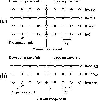
If the wavefields are sampled with spacing ![]() , then
equation (1) will image with half-offset spacing
, then
equation (1) will image with half-offset spacing
![]() , as shown in Figure 2 (a).
Sampling in offset can be refined further by considering
Figure 2 (b); however, to do so requires imaging onto
midpoints which do not lie on the propagation grid.
, as shown in Figure 2 (a).
Sampling in offset can be refined further by considering
Figure 2 (b); however, to do so requires imaging onto
midpoints which do not lie on the propagation grid.
|
cmpboth
Figure 2 Imaging offsets (a) with |  |
This problem is experienced whenever data are transformed from shot-geophone to midpoint-offset space, and no perfect solution exists. A typical workaround is to refine the midpoint grid, and fill empty bins with zeros; however, this doubles the data-volume and hence also doubles the cost of migration. Another alternative is to process even and odd offset separately; the disadvantage of this approach is that each half of the dataset may be undersampled.
By working in the shot-geophone domain, these problems are avoided until after the migration is complete. Migration decreases the data-volume, increases the signal-to-noise ratio, and resolves locally conflicting dips. Therefore, it is easier to resample the data on whatever grid suits the interpreter after migration.