

Next: Discussion
Up: Mora: AVA in angle
Previous: Synthetic data
I applied three different processing sequences
to each data set in order to compare the resulting amplitudes from
angle-domain common-image gathers with the amplitudes from
offset-ray parameter images.
- 1.
- Prestack wave-equation migration with output in offset domain +
conversion to angle gather by Fourier transform.
- 2.
- Prestack wave-equation migration with output in offset ray parameter
domain.
- 3.
- Iterative execution of prestack wave-equation migration and inversion
with output in offset ray parameter domain (10 iterations).
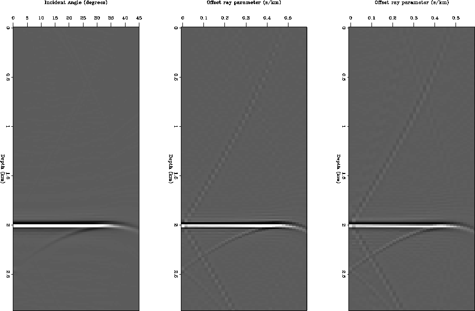
Figure 3 shows the resulting CIG gathers for each
processing sequence in model 1 and Figure 4 shows
the resulting CIG gathers in model 2.
image-con-all
Figure 3 CIG result of applying the
3 processing sequences to model 1.
Left: Prestack wave-equation migration with output in offset domain +
conversion to angle gather by Fourier transform.
Middle: Prestack wave-equation migration with output in offset ray parameter
domain.
Right: Iterative execution of prestack wave-equation migration and inversion
with output in offset ray parameter domain.


 image-avo-all
Figure 4 CIG result of applying the
3 processing sequences to model 2.
Left: Prestack wave-equation migration with output in offset domain +
conversion to angle gather by Fourier transform.
Middle: Prestack wave-equation migration with output in offset ray parameter
domain.
Right: Iterative execution of prestack wave-equation migration and inversion
with output in offset ray parameter domain.


We can see some artifacts that are stronger in cases 2 and 3. These artifacts
could affect the amplitudes values in the near and far offset.
Also, for cases 2 and 3, the output is in the offset ray parameter
domain which is not directly the angle
of incidence; the offset ray parameter, phx,
is related to the aperture angle  , the dip
  along the
in-line direction, and the velocity function
  ,as follows Prucha et al. (1999):
|  |
(1) |
Therefore, for cases 2 and 3, I calculated the conversion to the angle domain
using the relation from equation (1).
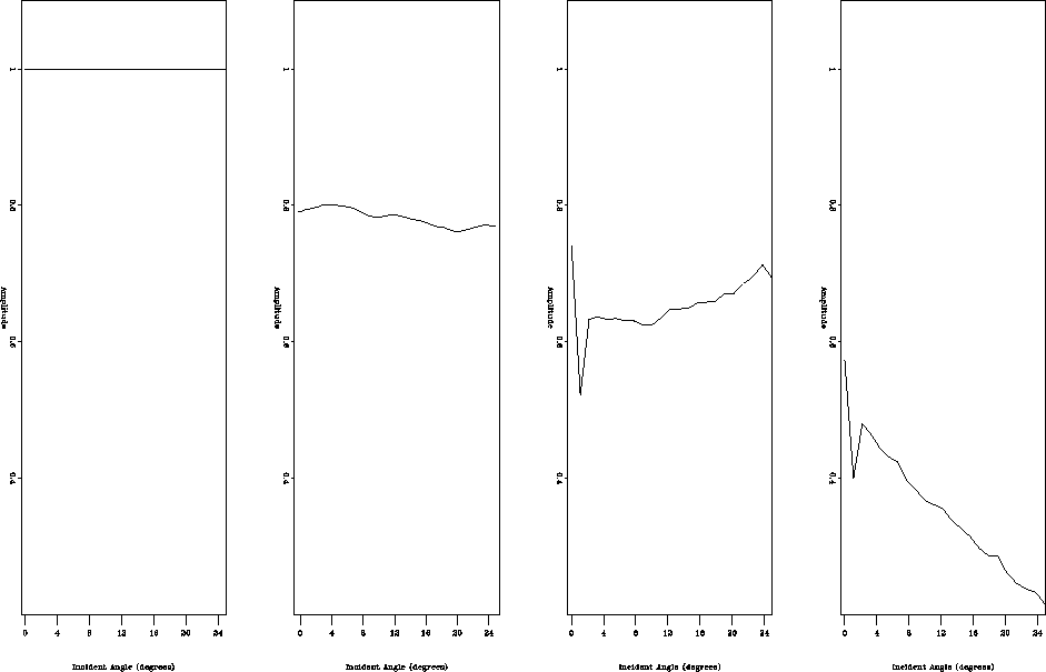
Figure 5 shows the picked amplitudes at the flat interface
in the migrated CIG gather for model 1.
con_all
Figure 5 Picked amplitudes at the
flat reflector for model 1:
before migration (left), after migration and angle gather conversion
(middle left),
after migration (middle right) and conversion to angle domain,
after migration/inversion and conversion to angle domain (right).


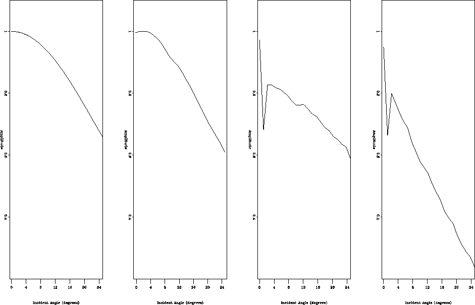
Figure 6 shows the picked amplitudes at the flat
interface in the migrated CIG gather for model 2.
avo_all
Figure 6 Picked amplitudes at the
flat reflector for model 2:
before migration (left), after migration and angle gather conversion (middle left),
after migration (middle right) and conversion to angle domain,
after migration/inversion and conversion to angle domain (right).


Next: Discussion
Up: Mora: AVA in angle
Previous: Synthetic data
Stanford Exploration Project
4/29/2001


