


Risk assessment is a key component to any business decision. Geostatistics has recognized this need and has introduced methods, such as simulation, to attempt to assess uncertainty in their estimates of earth properties. Geophysics has been slower to recognize this need, as methods which produce a single solution have long been the norm.
The single solution approach, however, has a couple of significant drawbacks. First, because least-square estimates give invert for the minimum energy/variance solution, our models tend to have low spatial frequency than the true model. Second, it does not provide information on model variability or provide error bars on the model estimate. Geostatisticians have both of these abilities in their repertoire through what they refer to as ``multiple realizations'' or ``stochastic simulations.'' They introduce a random component, based on properties of the data, such as variance, to their estimation procedure. Each realization's frequency content is more representatitve of the true model's and by comparing and contrasting the equiprobable realizations, model variability can be assessed.
In previous works Clapp (2000, 2001), I showed how we can modify standard geophysical inverse techniques by adding random noise into the model styling goal to obtain multiple realizations. Claerbout (1998) shows how an estimate of the correct scaling for the random noise can be obtained for the missing data problem. In this paper, I extend this early work. I show how we can modify the data fitting goal in a parallel manner achieving a potentially more significant result. By adding random noise colored by the inverse data covariance, we can obtain multiple model estimates that show how data uncertainty map to model uncertainty. In terms of velocity estimation we can rephrase this relation as how our uncertainty in semblance picks affects our estimate of interval velocity.
In this paper I begin by reviewing the methodology of adding noise to the model styling goal. I show why and when the methodology is effective. I then show how we can encode data uncertainty into our model estimation. I conclude by demonstrating both techniques on simple 1-D and 2-D tomography problems.
REVIEW: INCORPORATING MODEL VARIANCE
In Clapp (2001), I began with
the standard geophysical problem,
a linear relationship
![]() between a model
between a model ![]() and
and ![]() , with a regularization
operator
, with a regularization
operator ![]() , written in terms of fitting goals as:
, written in terms of fitting goals as:
| (1) | ||
| |
(2) | |
| |
(3) |
| |
(4) | |
|
wood.hole
Figure 1 A wood texture from Claerbout (1998) with a hole removed to simulate a missing data problem. | 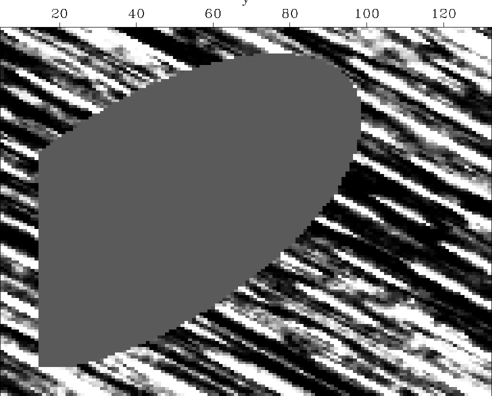 |


|
wood.pef
Figure 2 The result of solving a missing data problem using the data in Figure 1 as input, a PEF found from the known data locations, and fitting goal (3). |  |
![[*]](http://sepwww.stanford.edu/latex2html/movie.gif)
|
wood.histo
Figure 3 Left panel is the histogram of the known data locations shown in Figure 1. The right panel is the histogram of the residual at the same known locations after applying fitting goal (3). Note how the almost uniform distribution of the data approaches a normal distribution. | 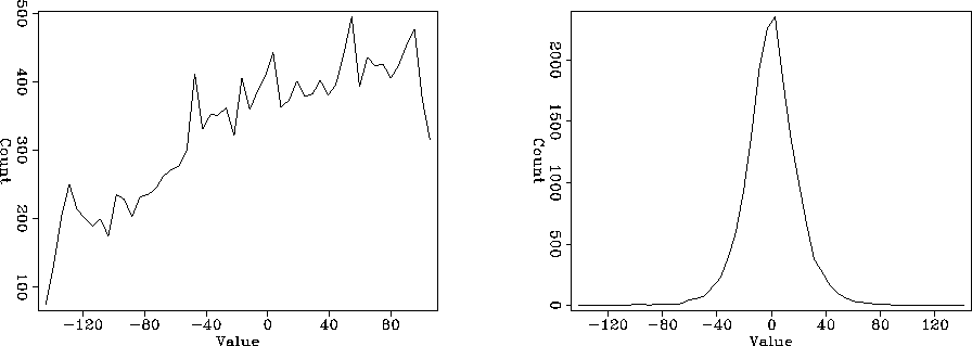 |
 |
Comparison to geostatistics The most common method to create models that the honor both first and second order statistics is geostatistical simulation. A comparison between the method presented in this paper and the standard geostatistical technique is therefore warranted.
For the comparison I will begin by describing the general procedure in sequential Gaussian simulation. First, some decision on stationarity is made. The known data is transformed to a new function that is standard normal. The covariance is described through variograms. Each point in the model space is randomly visited. At each point they find the best linear combination of known data, and points previously estimated through kriging Isaaks and Srivastava (1989), based on the predetermined variogram model. At the same time they calculate a kriging variance, which can be considered a measure of the uncertainty of the estimated value based on the surrounding points. A random number is then selected from a distribution function that has the calculated kriging mean and variance.
Each step in the geostatistical simulation procedure has a
corollary in an operator based simulation.
We begin by making a decision on stationarity. If the problem
is non-stationary, we can break the problem into patches Claerbout (1992)
(what
geostatiscians call ``distinct sub-zones'' ) or we can use a
non-stationary covariance
description Clapp et al. (1997); Crawley (2000) (geostatisticians use kriging
with external drift to allow some degree of non-stationarity).
We transform into a space that is Gaussian (if we have an accurate
description of the model's covariance function, the residual
space will have a Gaussian distribution). The operator approach
solves a global, rather than a local, problem. The kriging estimate
corresponds to our PEF estimated with a ![]() in the model
styling residual. Finally, the kriging variance corresponds to
the variance of the residual in the PEF estimation.
in the model
styling residual. Finally, the kriging variance corresponds to
the variance of the residual in the PEF estimation.
Uses Introducing model variance into the estimation process has several attractive properties. For missing data problems, we can produce models that have a more realistic texture and behave more accurately when used as inputs as for processes such as fluid flow. We can quickly test the accuracy of our covariance description by applying
| |
(5) |
 |
When we have a more complex mapping operator, introducing model variability can help us understand the null space of our mapping operator. This can be potentially interesting for understanding Amplitude Versus Offset (AVO) effects from standard velocity estimation techniques Mora and Biondi (1999, 2000).
What the method doesn't address is a potentially more interesting question: how does data uncertainty map to model uncertainty? In the next section, I will propose a methodology for addressing this issue.
DATA UNCERTAINTY
To understand the method that I am proposing, let's begin by rewriting our standard fitting goals. We normally write
| (6) | ||
| (7) | ||
| (8) | ||
There is a corollary way to think about data variance.
Normally we limit our characterization of data covariance to
a diagonal
matrix often referred to as the weight operator ![]() .A more appropriate
choice is the data covariance matrix. We can rewrite our
system of equations
and add in an appropriate level of data variance:
.A more appropriate
choice is the data covariance matrix. We can rewrite our
system of equations
and add in an appropriate level of data variance:
| (9) | ||
| (10) |
Given this formulation we can define perturbed ![]() through
through
| (11) |
Super dix To test the methodology, I will return to the Super Dix example Clapp et al. (1998); Clapp (2000); Rosales (2000). In 1-D we write the Super Dix fitting goals as
| (12) | ||
|
model-var
Figure 6 Effect of changing the model variance on interval velocity. | 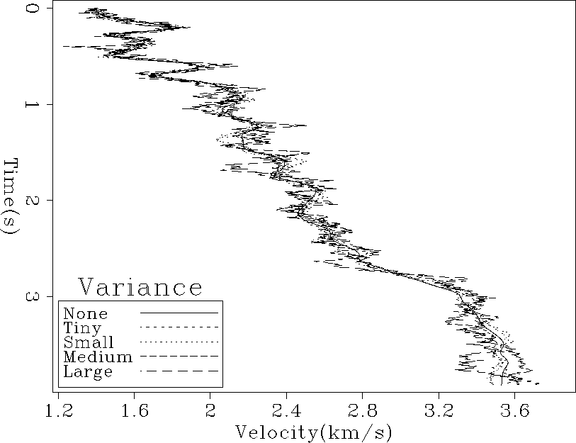 |
|
data-var
Figure 7 Effect of changing the data variance on interval velocity. |  |
2-D example We can extend the basic 1-D formulation into 2-D. We redefine our data by
| |
(13) |
| |
(14) | |
| (15) |
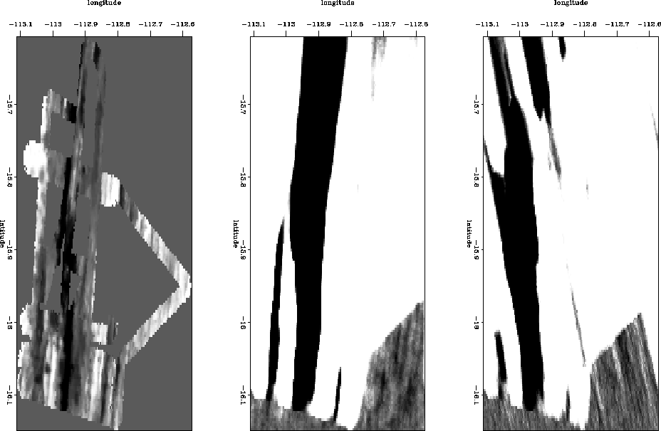
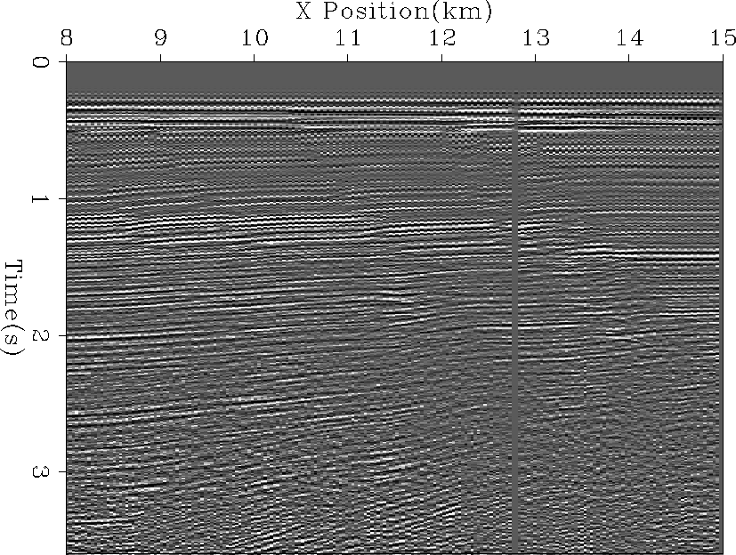
To test the methodology I chose the relatively simple Gulf of Mexico dataset
provided by Western and used in Claerbout (1995).
Figure 8 shows a near offset section from the data.
I performed semblance analysis and chose a fairway within which
all valid ![]() picks would fall (Figure 9).
For each CMP, I automatically picked the maximum semblance at
each time within the fairway (Figure 10).
For my diagonal operator
picks would fall (Figure 9).
For each CMP, I automatically picked the maximum semblance at
each time within the fairway (Figure 10).
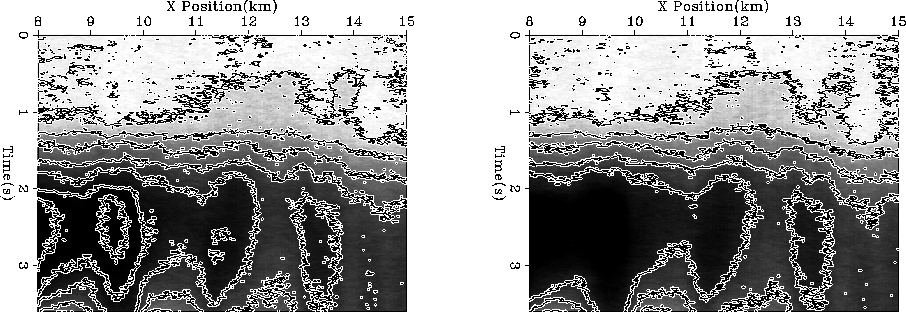
For my diagonal operator ![]() , I used the amplitude of the semblance
at the picked vrms (left panel of Figure 11)
and then scaled by 1/t to correct for
, I used the amplitude of the semblance
at the picked vrms (left panel of Figure 11)
and then scaled by 1/t to correct for ![]() being the result of summing
operation.
being the result of summing
operation.
 |
|
fairway
Figure 9 Semblance analysis for a CMP from the data shown in Figure 8. Overlaid is the fairway used by the automatic picker. | 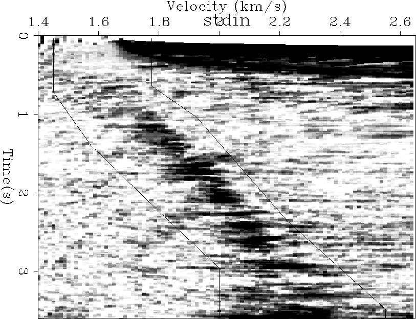 |
|
rms
Figure 10 The automatically picked velocities for each CMP within the fairway shown in Figure 9. Overlayed are smoothed contours for the same field. | 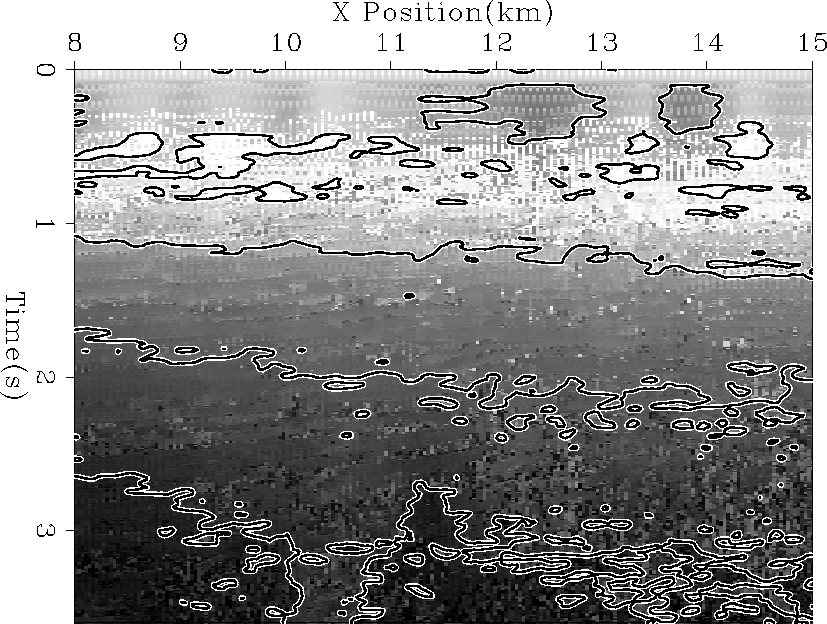 |
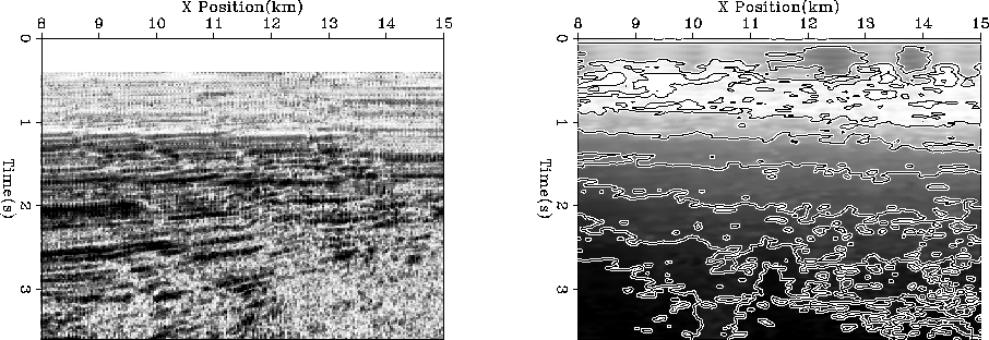 |
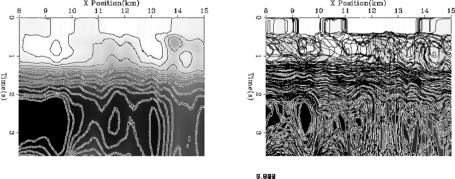
Figure 12 shows the result of estimating an interval velocity
without adding any model variance or data uncertainty.
Figure 13 shows two different realizations for
the interval velocity adding model variability.
I estimated a PEF from my vrms picks and used filtering
with that PEF for ![]() and polynomial division with it for
and polynomial division with it for ![]() .For my data variance I used the width of the picked semblance block
(the right panel of Figure 11). Note how, as expected,
the variance generally increases with depth.
For my different data realizations I applied equation (14).
Figure 14 shows two different realizations
of the interval velocity using the data with the added uncertainty.
.For my data variance I used the width of the picked semblance block
(the right panel of Figure 11). Note how, as expected,
the variance generally increases with depth.
For my different data realizations I applied equation (14).
Figure 14 shows two different realizations
of the interval velocity using the data with the added uncertainty.
|
int
Figure 12 The result of estimating for an interval velocity from the vrms picks in Figure 10 without adding any model variance or data uncertainty. Overlaid are contours for the same field. | 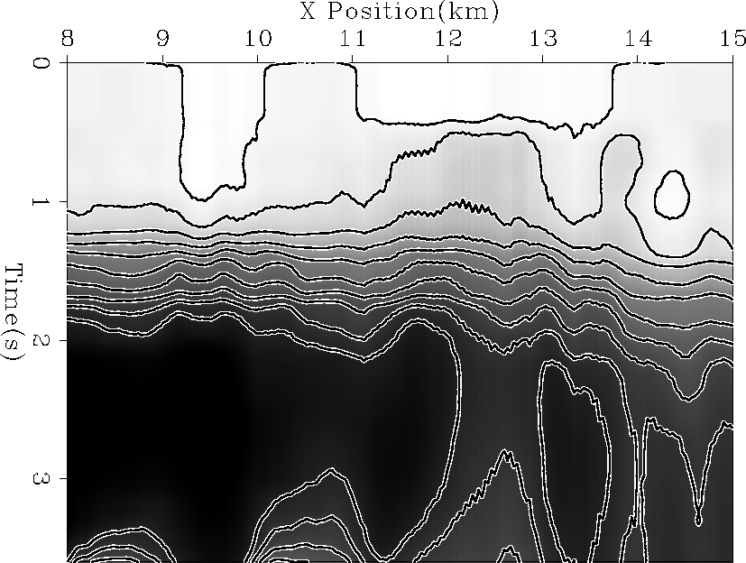 |
 |
 |