


On data with complicated dips, nonstationary filters work better than stationary filters. Noise is a problem related to the problem of complicated dips. Regone 1998 points out that in many cases, noise which appears to be random is completely repeatable, though incoherent. Energy may be scattered by near surface features back to receivers at many different angles and amplitudes simultaneously. This superposition of waves at all angles may produce what looks like random noise, but as long as the shot and receiver positions do not change, the same scattered energy will be produced by successive shots, and the apparently random noise will be recreated.
That may mean that apparently random noise should be interpolated, because it is just many superimposed plane waves. On the other hand, maybe genuinely random noise will be interpolated if we allow our filters too much freedom by making them large, since the number of plane waves predicted by a PEF depends on its size. In the end the important thing is to interpolate all of the coherent events that exist in the data, and to not create any new coherent events from random noise.
We do not attempt any distinction between signal and coherent noise. Coherent noise should be interpolated. In the case of multiples, this is often exactly the point of the interpolation. Interpolating the multiples dealiases them and makes them easier to suppress.
Noisy data examples: confirmation of Abma's result
Abma 1995 shows that (t,x) PEFs are less likely to create spurious events in the presence of noise than (f,x) PEFs, because calculating a filter at each frequency is the time domain equivalent of calculating a filter that is long on the time axis. This effective time length of the (f,x) filter gives it sufficient freedom to predict ostensibly random noise.
As an example, the data used in Figures 355start.shot through 355recsub.out.shot is used again, except noise is added, and the PEFs used for interpolation are only two dimensional. The other examples in this thesis have three or more dimensions, but the (f,x) interpolation that I happened to have available for comparison uses two dimensions in the input, so for this test the interpolation is 2-D in both domains. My experience has been that (t,x,y) interpolation nearly always gives better results than just (t,x); presumably the same is true for (f,x,y) and (f,x). So in both domains the results could be better, but they should still make a meaningful comparison.
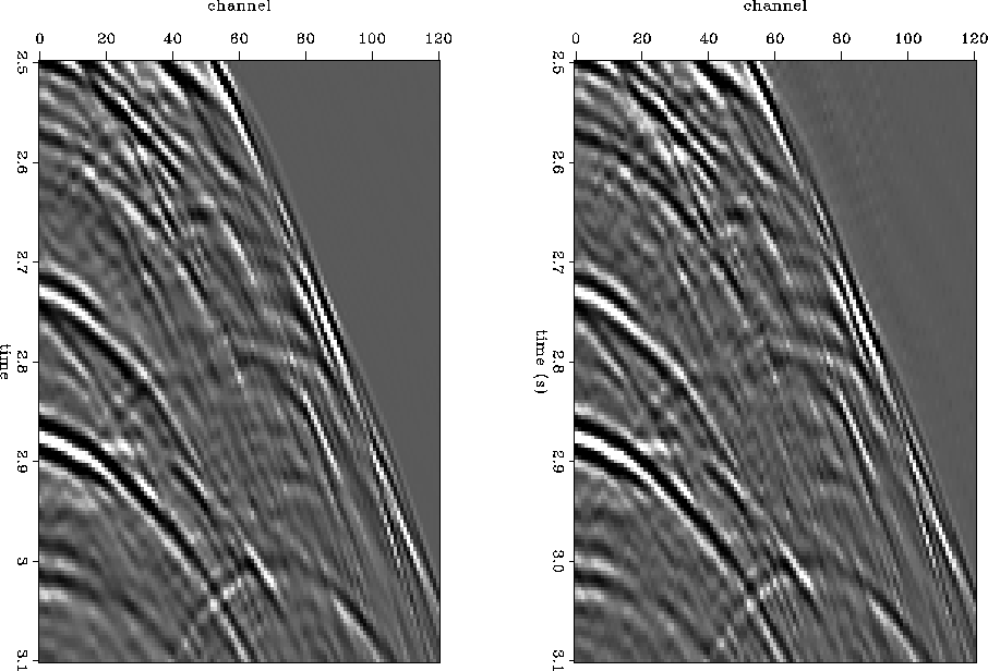
The data as it was recorded has little noise. On noise-free data, time- and frequency-domain implementations both produce fine results. Figure 102.smooth.both.out.closeup shows closeups on results of interpolating noise-free data using (t,x) interpolation on the left, and (f,x) on the right. The data were subsampled on the x-axis simulating receiver gathers with alternate shots missing, and then reinterpolated. The time-domain interpolation uses the PEF smoothing scheme described in chapter 3. The panels in Figure 102.smooth.both.out.closeup are not identical, but either is a good result.
 |

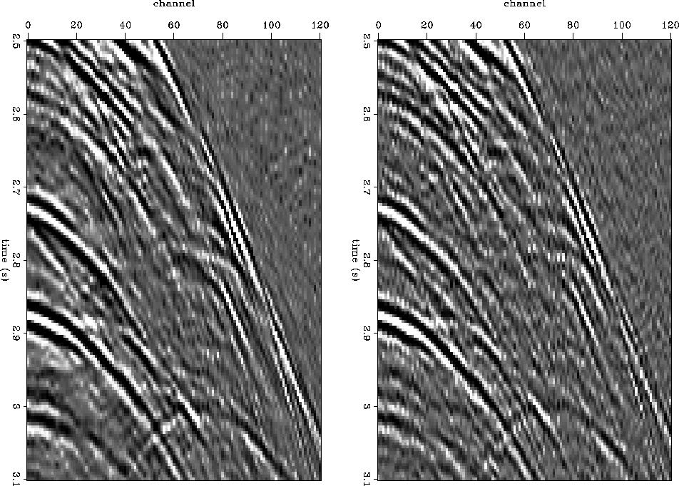
With increasing amounts of noise, the difference between time-domain and frequency-domain interpolation becomes significant. Random noise was added to the same data and interpolated again, to produce the results in Figure 102.sn.both.cp. Again, time domain is on the left, frequency on the right. Where either domain did a satisfactory job on the noise-free data, the time domain produced a significantly better result on the noisy data. Many of the strong events are better interpolated in the time domain. Also, as a confirmation of Abma's observation, in the time domain there is almost no interpolation where there are no coherent seismic events, such as above the seafloor reflection where the only energy is the added noise. Where there is nothing but white noise to interpolate, nothing happens, because PEFs are just whiteners. In the frequency domain, the noise is interpolated. The same amount and distribution of noise is added in both cases, but the frequency-domain result looks noisier because more noise is interpolated into the new traces.
 |
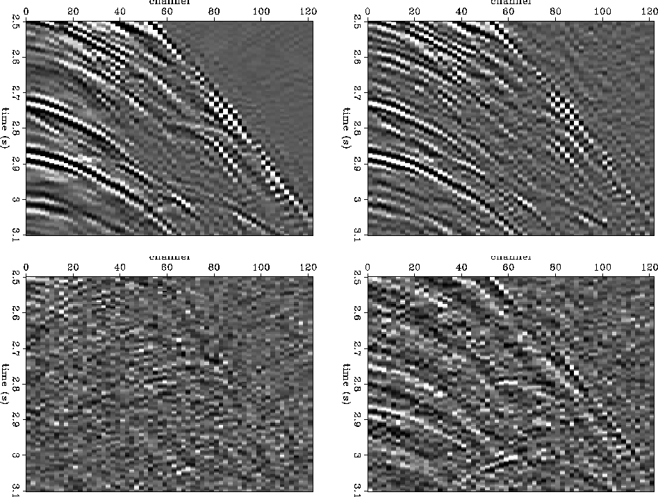
The differences between the two results are easier to see in Figure 102.sn.all.cpd. The top half of this figure shows the same two panels as Figure 102.sn.both.cp, with the known half of the traces removed. The top left shows just the energy interpolated into the missing traces in the time domain. The top right shows just the energy interpolated into the missing traces in the frequency domain. The time domain method adds much less energy above the first breaks, where there is nothing to interpolate, though both methods add a slight artifact above the first breaks and parallel to them. More importantly, the time domain method does a better job at interpolating dips pointed both out towards increasing offset and in towards zero offset. For example, the event with its apex at about channel 70, at time 3.0 s, is better interpolated in the time domain. The near offsets and the steep events around the first breaks also look better in the time domain result.
The bottom half of Figure 102.sn.all.cpd shows difference panels between the interpolation result and the original traces which were thrown out. The left is time domain, the right is frequency. Again, the known half of the traces are not shown, since they naturally have a difference of zero. Both differences have noticeable energy, but the time domain difference is mostly incoherent. The frequency domain difference shows some definite coherent events. In particular the near offset events, the first break events, and the mid-offset event at 3.0 s all show up in the frequency domain difference panel.
 |