

Next: Data
Up: Review
Previous: Characterizing moveout errors
To set up our tomography problem we need to cover
some final details.
We can convert our semblance picks back into a  shift by
applying
|  |
(8) |
We then note that our tomography problem is set up for time rather
than depth errors,
To convert our depth error to a time error
we multiplying by RMS slowness srms of.
If we use a straight ray geometric assumption, we can approximate the time error
at a given offset by multiplying by  and
and  (where
  is the geologic dip) obtaining
as our final relationship
|  |
(9) |
In constructing our raypaths we benefit from having our
CRP gathers in terms of angle. If errors were in
terms of offset we would have to either
- shoot rays from every source and receiver location, and find
ray pairs that obey Snell's law at the position on the reflector imaged
at the offset dictated by the ray pair
- or shoot rays from our CRP locations along where our reflector is
imaged at every offset and then interpolate the ray field
to our source and receiver locations.
Both options require significant additional ray-tracing in 2-D, and
even more in 3-D. In addition, we are always faced with the tradeoff of
how much should we interpolate our rays versus how many additional rays
should we shoot.
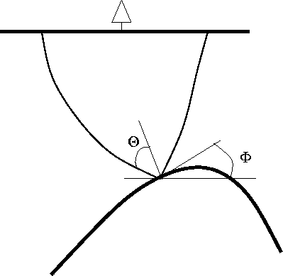
With our moveout errors in terms of angle we only
need to shoot a single ray-pair up
from our imaging point at the angle  and
and  ,
,
|  |
(10) |
| |
where  is one-half
the aperture angle,
  is the geologic dip
(Figure 1).
If the rays emerge at surface locations corresponding to an
offset and CMP location inside our acquisition geometry we have a valid ray pair.
sketch
Figure 1 How the takeoff angle for a ray-pair
are defined.
|
|  |


Next: Data
Up: Review
Previous: Characterizing moveout errors
Stanford Exploration Project
4/28/2000
![]() and
and ![]() ,
,
