


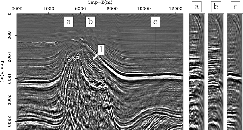
Figure 3 shows a typical set of sections in the middle of the migrated cube. In the in-line section, the shallower part down to 1500m reveals high frequency details accurately imaged. The migration enhanced a graben structure, with normal faults and rocked blocks, around location Cmp-X=8000m, close to the top in the sand layer. The most energetic interfaces in the section, located approximately at depth 1500m, correspond to the limit tertiary/chalk in the geologic interpretation presented in Figure 1. The velocity model indicates a strong velocity contrast there, with more than 1000m/s difference between the two media.
 |


The horizontal section at depth 900m highlights complex patterns inside the tertiary layer, imaged with a high resolution. Those can be interpreted as turbidite channels. The main direction of slumping is along the in-line, away from the salt dome. We can infer as a hypothesis that the upcoming salt may be the cause of the flow and of the resedimentation.
Both the depth section and the cross-line section show an oblique fault through the chalk layer just above the salt body. On one side of the fault inside the chalk appears a strong reflector, like a block of salt separated from the main body, or perhaps another lithologic feature. The bottom interface of the chalk layer with the Lias is imaged accurately.
The salt body in itself is well delimited on its right side. The top-left boundary is well focused after migration, though with a weaker amplitude. Although we can observe the sediments in the chalk bent upwards by the upcoming salt on the left-hand side, the boundary itself is not clearly recovered by the migration. We expect it to be almost vertical, with the beginning of the overhang below depth 2500m. In the cross-line direction, the top of salt reveals a complex shape, as seen in that section. The imaging there seems satisfactory, and the top of salt is quite continuous.
Seismic imaging can be sketched as a two-step process: velocity estimation and migration. All modern migration algorithms require a simple and reliable way to extract prestack information for velocity estimation and updating. For this purpose, 3-D angle-domain common-image gathers can be easily computed in the wavenumber domain from the output of common-azimuth migration Prucha et al. (1999); Sava (1999). Those panels enhance valuable information for analysis when the velocity model is complex and induces multi-pathing.
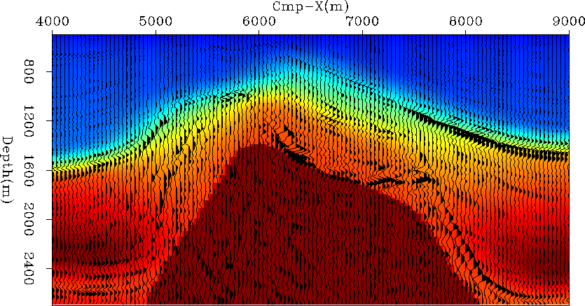 |
Figure 5 shows the same in-line section as before (Cmp-Y=3400m), with examples of the angle-domain common-image gathers that can be obtained from the migrated image. Unlike the image in figure 3, the section is not a stack over the angle axis but instead a near-angle image. Even if it increases the noise level, it also displays more events that are not stacked coherently because the velocity is not perfect. For the sake of clarity, we will next focus on this particular in-line section and will use it as a support for the analysis of our migration results.
 |
In figure 5, panels (a) and (b) show that the reflectors corresponding to the interface Tertiary/salt are well aligned along the angle axis. Similarly, in panel (c), the complex interface chalk/Lias/Trias at the bottom-right of the section reveals flat gathers. The velocity at these interfaces is well determined. The top and the left-hand side of the salt body (panels (a) and (b)) are not perfectly flattened in the gathers. The inclusion labeled ``I'' above the salt that causes an energetic reflection yields a slightly high velocity anomaly since it is not accounted for in the velocity model (see figure 4).