

Next: Conclusions
Up: Migration results of the
Previous: Comparison of common-azimuth migration
The velocity above the salt body does not vary rapidly in the lateral
directions.
Therefore the images obtained by the hybrid offset plane wave migration (B)
and the ``real'' offset plane wave migration (C)
are very similar.
On the contrary, below the salt body,
the approximation introduced by downward-continuing
the offset plane wave separately causes
significant problems in the imaging of the sub-salt reflectors.
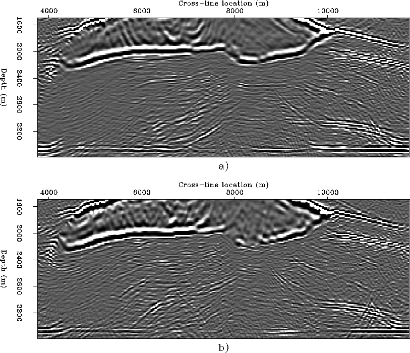
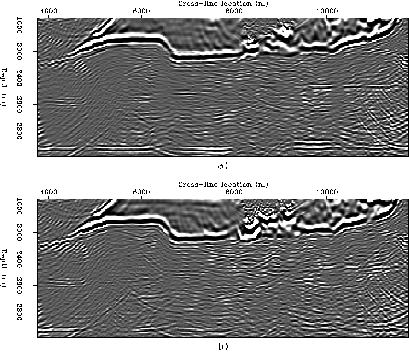
The next four figures compare the deeper portion
(starting from a minimum depth of 1,500 m)
of two in-line sections
and two cross-line sections obtained by migrations (A) and (C).
The sub-salt images are considerably
noisier than the above-salt images.
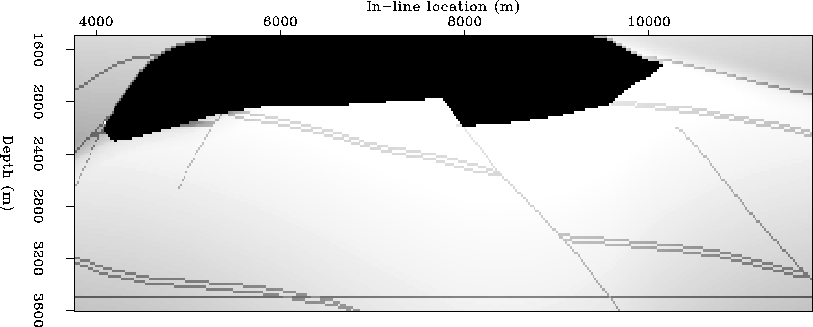
To facilitate the analysis,
I show also the corresponding sections of the velocity model.
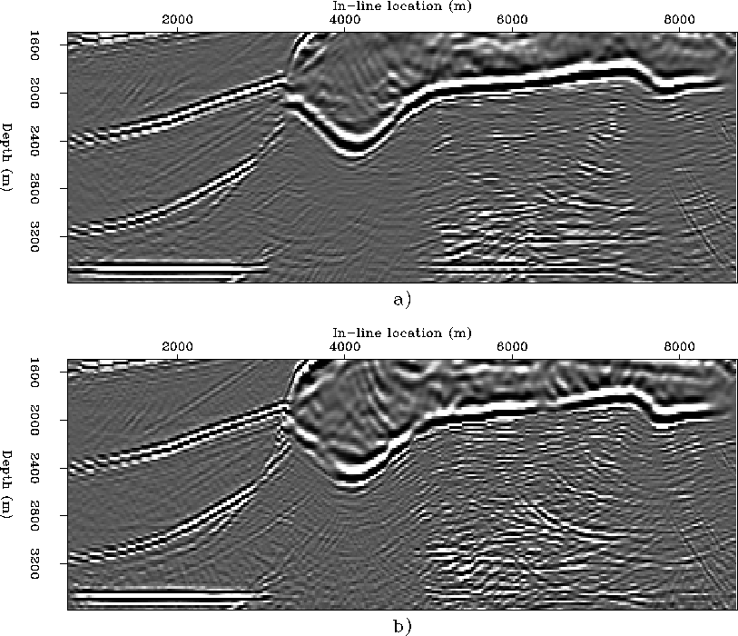
Figure 8 compares the
in-line sections obtained by
common-azimuth migration (A)
and the offset plane wave migration (C);
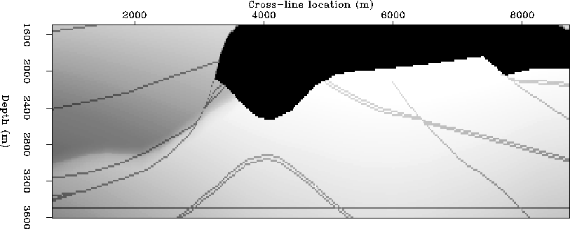
Figure 9
shows the corresponding section of the velocity model.
The bottom of the salt body,
and in particular the dipping segment at the
left edge of the salt,
is better imaged by migration (A)
than by migration (C).
In the shadow of the salt body,
the image of the basement is also more continuous
in panel a) than in panel b).
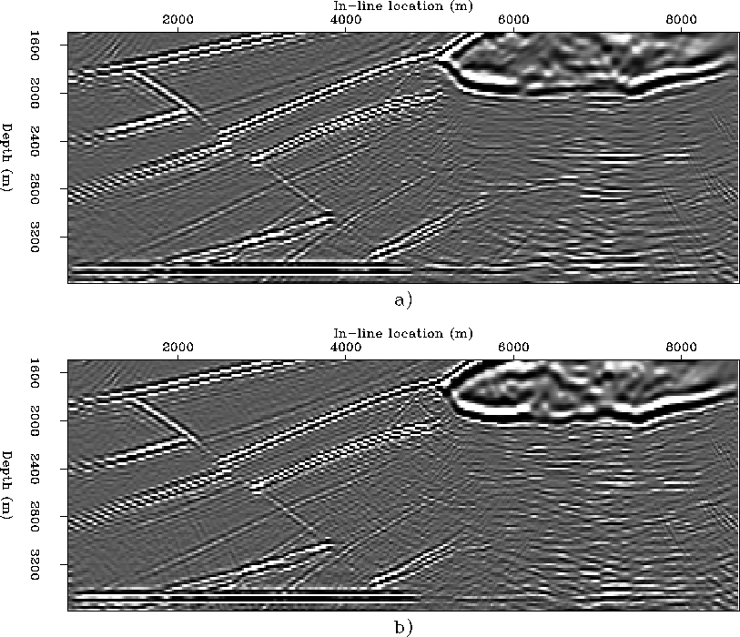
Figure 10 compares the
in-line sections obtained by
common-azimuth migration (A)
and the offset plane wave migration (C);
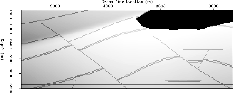
Figure 11
shows the corresponding section of the velocity model.
Both sand lenses visible in the right part
of the sections are better imaged by migration (A)
than by migration (C);
in particular, the deeper lens just above the basement reflector
is more clearly defined in panel a) than in panel b).
The image of the basement is also more continuous
in panel a) than in panel b).
Possibly the most interesting difference is in the imaging
of the anticlinal structure broken by converging normal faults
visible in between the two sand lenses.
Migration (A) produces an image, though fairly faint,
of this structure even in the shadow of the salt body.
In contrast,
the structure disappears from the image produced by
migration (C) as soon as it gets in the shadow of the salt body.
Figure 12 compares the
cross-line sections obtained by
common-azimuth migration (A)
and the offset plane wave migration (C);
Figure 13
shows the corresponding section of the velocity model.
The dipping segment of the bottom of the salt that
belongs to the fault plane cutting through the salt body
(cross-line location 8,000 m)
is better imaged by migration (A)
than by migration (C).
The basement reflector is also more continuous
in panel a) than in panel b).
Figure 14 compares the
cross-line sections obtained by
common-azimuth migration (A)
and the offset plane wave migration (C);
Figure 15
shows the corresponding section of the velocity model.
As for the in-line sections shown in Figure 10,
both sand lenses visible in the right part
of the sections are better imaged by migration (A)
than by migration (C).
Though discontinuous in places,
the basement reflector is also
better imaged by migration (A)
than by migration (C).
The bottom of the salt reflector right below
the deep canyons in the salt body (in-line location 8,000-9,200 m)
is fairly coherent in panel a),
while it is discontinuous in panel b).
Both-salt-under-x6300
Figure 8
In-line sections (cross-line location 6,300 m) from the images obtained with
a) common-azimuth migration (A),
b) offset plane wave migration (C).


Vel-salt-under-x6300
Figure 9
In-line section of the velocity model at cross-line location 6,300 m.


Both-salt-under-x9980
Figure 10
In-line sections (cross-line location 9,980 m) from the images obtained with
a) common-azimuth migration (A),
b) offset plane wave migration (C).


Vel-salt-under-x9980
Figure 11
In-line section of the velocity model at cross-line location 9,980 m.


Both-salt-under-y5180
Figure 12
Cross-line sections (in-line location 5,180 m) from the images obtained with
a) common-azimuth migration (A),
b) offset plane wave migration (C).


Vel-salt-under-y5180
Figure 13
Cross-line section of the velocity model at in-line location 5,180 m.


Both-salt-under-y7300
Figure 14
Cross-line sections (in-line location 7,300 m) from the images obtained with
a) common-azimuth migration (A),
b) offset plane wave migration (C).


Vel-salt-under-y7300
Figure 15
Cross-line section of the velocity model at in-line location 7,300 m.


Next: Conclusions
Up: Migration results of the
Previous: Comparison of common-azimuth migration
Stanford Exploration Project
10/25/1999
