

Next: CONCLUSIONS
Up: Clapp & Biondi: Velocity
Previous: INTRODUCTION
To demonstrate how the tau back projection operator is less affected by
our initial slowness model, we constructed a simple 1-D synthetic.
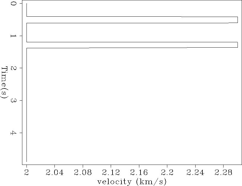
The model, Figure 2, is composed of two 2.3 km/s zones
in a constant 2 km/s background.
For this test we assumed that our slowness model had correctly resolved the
bottom anomaly in vertical travel time.
Our choice of vertical travel time is quite important, as
when doing velocity estimation, we must always
preserve zero-offset travel time.
In this simple 1-D synthetic, that means that the vertical travel-time to the
layer boundaries and to the reflector must be kept constant.
Therefore, in depth, we will misplace the location of
of the bottom high velocity zone but preserve the correct vertical
travel times to
the layer top and bottom.
After constructing the model we found the
ray that hit the reflector at 2 km depth, 2 km away from source in
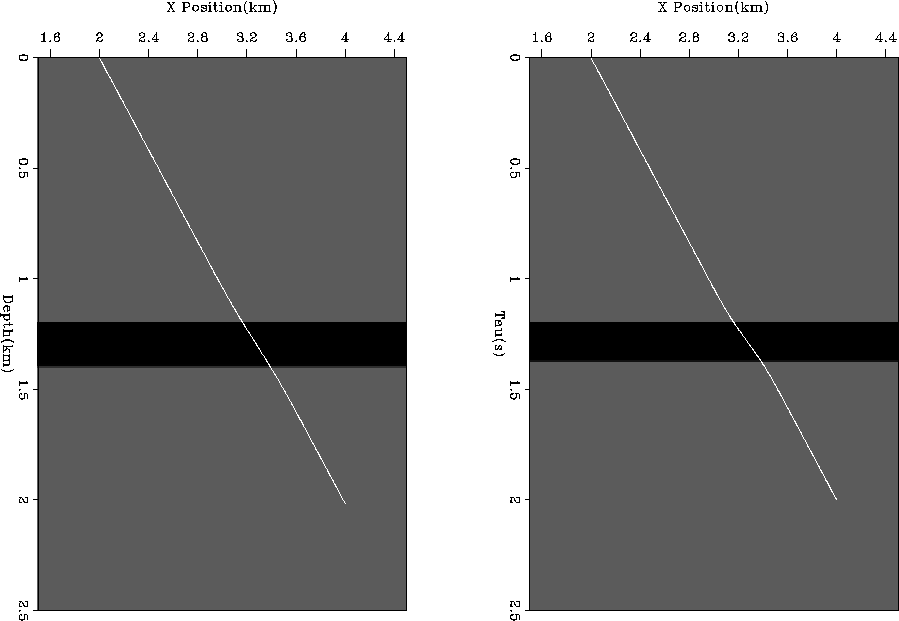
both ( ) and (z,x) space (Figure 3.)
Following the method outlined in Clapp and Biondi
1998,
we built the tomography operator for both
tau (
 ) and depth (
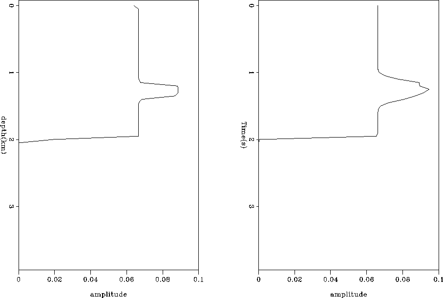
 ), Figure 4.
cor
Figure 2 Synthetic 1-D velocity function in  . . |
|  |


 vel0
vel0
Figure 3 Initial guess at the velocity function
overlaid by ray hitting reflector at 4 km with a half-offset of 2 km.
Left panel is in depth, right panel is in tau.


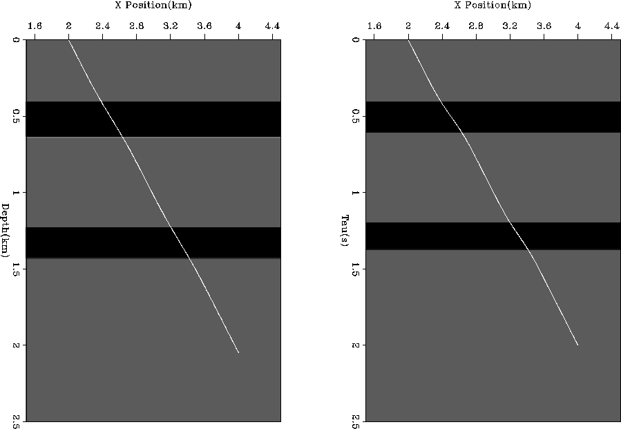
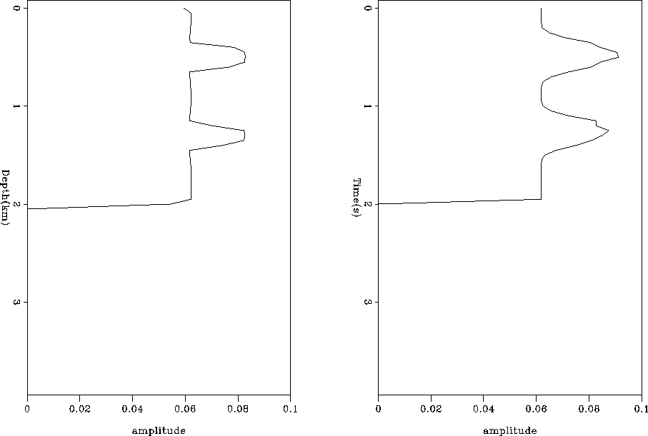
For comparison, we ray traced through the `correct' velocity
model in both spaces (Figure 5) and calculated the corresponding
operators. By comparing the correct and initial
operator for tau and depth, or by looking
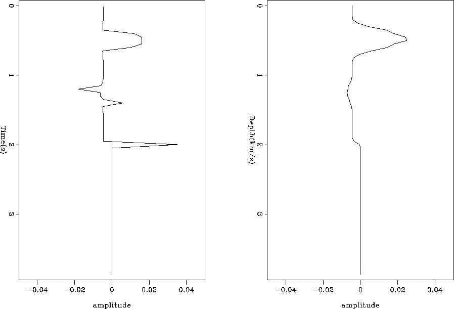
at the difference between the two operators (Figure 7), we
can clearly see that our initial guess for our tau operator is overall
better than our initial guess for our depth operator. In the upper
layer, we see marginally more change in the tau operator but at the
lower reflector boundaries (which move in the case of depth but remain
constant in tau) we see significantly more error in depth.
In addition, the change in reflector position has caused a spike
in the difference panel for the depth case.
Finally, the change in the tau operator is smooth, while the change
in the depth operator shows dramatic jumps. Our successive relinearizing
have an underlying assumption that we are smoothly converging to
the correct operator. In tau space, this assumption seems to be more valid.
With a more complicated model our positioning of layer boundaries,
will be subject to more change, making the tau compared to depth
difference even more dramatic.
operator0
Figure 4 The operator calculated from our initial guess
at velocity and the resulting ray paths in depth (left) and tau (right).


 vel1
vel1
Figure 5 ``Correct'' velocity function
overlaid by ray hitting reflector at 4 km with a half-offset of 2 km.
Left Panel is in depth, right panel is in tau.


 operator1
Figure 6 The operator calculated from the ``correct''
velocity and the resulting ray paths in depth (left) and tau (right).


 diff
diff
Figure 7 The difference between the operators calculated
from the correct and our initial guess at velocity, for depth (left) and
tau (right. Note the significant spikes at the reflector and at the lower
layer boundary in the depth case.


Next: CONCLUSIONS
Up: Clapp & Biondi: Velocity
Previous: INTRODUCTION
Stanford Exploration Project
4/20/1999


