|
|
|
|
Aligning microseismic reflections for imaging |
|
|---|
|
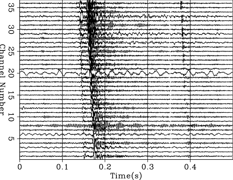
stack209-before
Figure 1. Stack of two seismograms aligned by bulk shifting. |
|
|
|
|---|
|
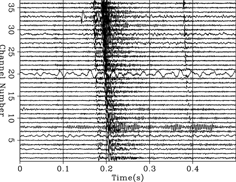
stack209-after
Figure 2. Stack of two seismograms aligned by warping. |
|
|
|
|---|
|
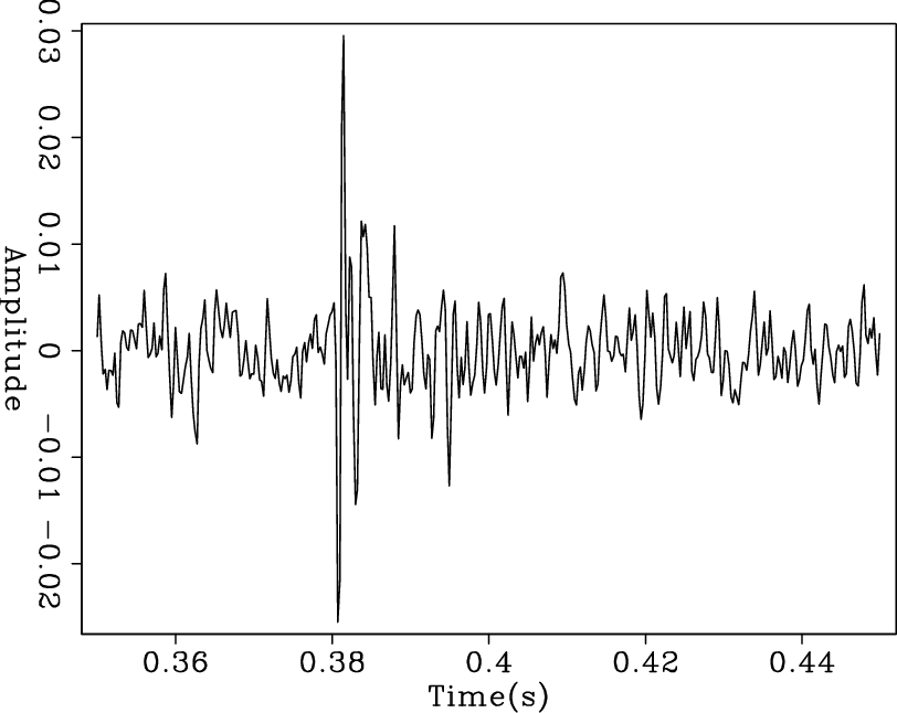
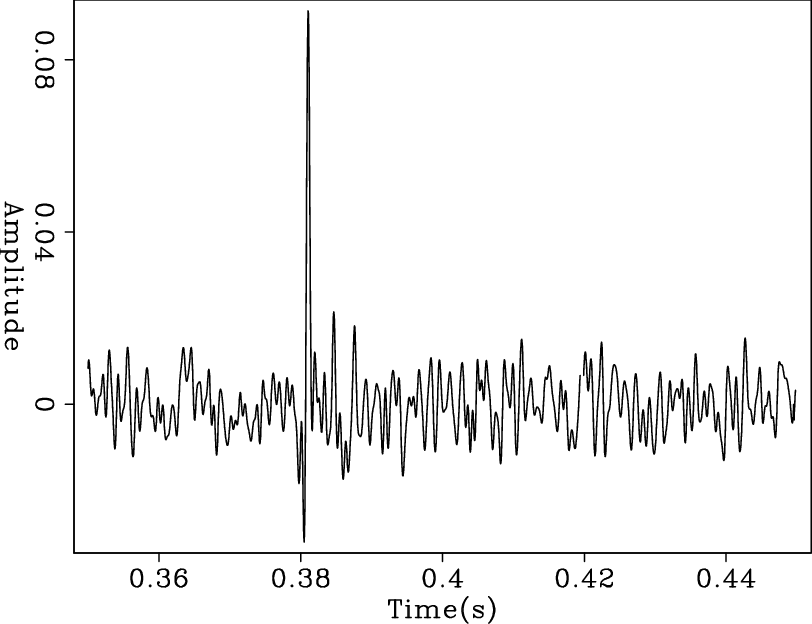
waveletbulk,waveletwarp
Figure 3. a) Selected reflection (30th channel) in a stack of 2 seismograms aligned by bulk shifting. b) Close up on the reflection (30th channel) in a stack of 2 seismograms aligned by receiver-by-receiver shifting (warping). Observe the increased peak amplitude after warping. |
|
|
|
|
|
|
Aligning microseismic reflections for imaging |