|
|
|
|
Imaging with multiples using linearized full-wave inversion |
|
|---|
|
illum-m
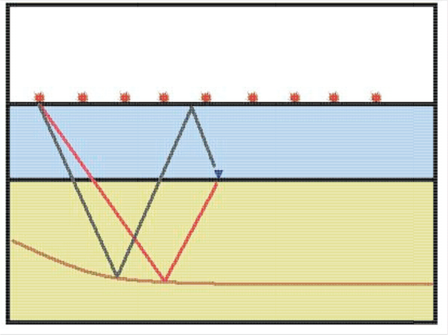
Figure 3. For a given pair of source and receiver, the sub-surface reflection point of a multiple event is different than that of a primary event. |
|
|
In an ocean-bottom survey, the signal (Figure 3) can be classified into up-going (in red) and down-going signal (in grey) with respect to the receivers. The lowest order of the up-going signal is the primary reflection. The lowest order of the down-going signal is the direct-arrival. Since the direct-arrival does not carry any information about the subsurface, the next order of down-going event, the mirror signal, is used for conventional migration of down-going OBN data.
We will referred the mirror signal as the down-going primary from now on. This is not to be confused with the up-going primary. One can apply LFWI on the ocean-bottom hydrophone recording without decomposing the up- and down-going signal. However, using only the hydrophone without up-down decomposition for imaging is less favorable due to the following reasons:
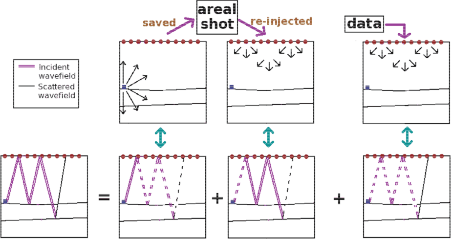
In this study, we focus on imaging different orders of down-going signals as shown in Figure 2 b and c. To simulate the final down-going leg of the wave path, an areal shot is pre-calculated by first injecting the source wavelet at the receiver location, letting the wavefield propagate, and then capturing the signal at the sea surface (Figure 4). To generate the incident wavefield, the saved areal shot is re-injected at the sea-surface with a -1 factor. The re-injected signal is then allowed to travel back and forth in the water column using a reflecting top boundary and a well-defined velocity contrast at the sea-bottom. This algorithm can correctly simulate the ray path traversed by the down-going primary and higher-order multiples.
|
|---|
|
Figure3
Figure 4. Illustration on the migration of the second-order signal. For the incident wavefield, an areal shot is pre-calculated to simulate the final down-going leg of the wave path. To generate the incident wavefield, the saved areal shot is re-injected at the sea-surface with a -1 factor. The re-injected signal is then allowed to travel back and forth in the water column using a reflecting top boundary and a well-defined velocity contrast at the sea-bottom. |
|
|
The focus of this report is on imaging the higher-order multiples for OBN data with the method illustrated in Figure 4. In particular, we compare the image output between migration with the down-going primary and LFWI with both the down-going primary and the down-going multiples.
|
|
|
|
Imaging with multiples using linearized full-wave inversion |