|
|
|
|
Edge-preserving smoothing for segmentation of seismic images |
|
|---|
|
syn-smth,syn-mhn
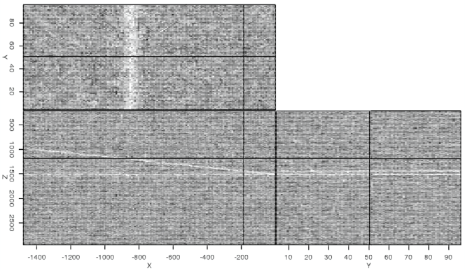
Figure 3. Results of smoothing the image in Figure 2 with (a) traditional box smoothing, and (b) maximum homogeneity (MH) filtering of the same operator length. |
|
|
|
|---|
|
syn-diff-smth,syn-diff-mhn
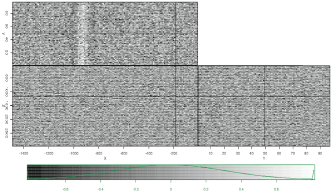
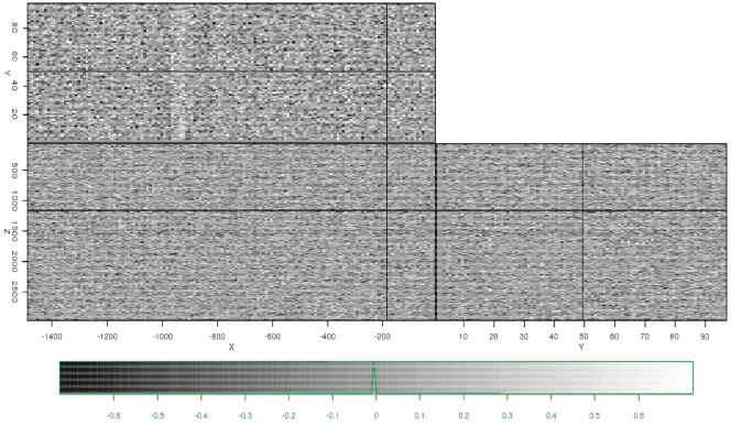
Figure 4. Results of differencing the images in Figures 2 and 3. The filtered information when using the MH filter (b) contains much less coherent signal than when using traditional smoothing (a). |
|
|
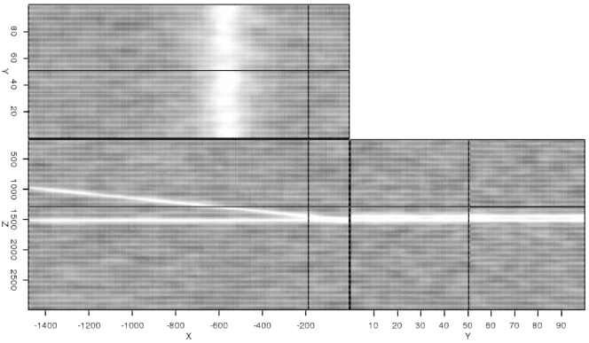
Ideally, smoothing the noisy image would clean up the image, and allow an interpreter to clearly see where the reflectors intersect. However, a traditional 5x5x5 box filter fails to produce this result (Figure 3(a)). While much of the noise is indeed removed, the filter has blurred the reflectors, making it impossible to distinguish between them. Furthermore, taking the difference between the noisy image and the filtered image gives an unwanted result (Figure 4(a)); it is obvious that a significant amount of coherent signal has been removed. In contrast, the maximum homogeneity (MH) filter with a mask length of 5 pixels performs better (Figure 3(b)). Not only are the two reflectors able to be distinguished much more easily in the filtered result (Figure 3(b)), but the difference calculation (Figure 4(b)) shows much less coherent signal being removed. Despite these advantages, though, more noise does remain in the MH-filtered image.
|
|
|
|
Edge-preserving smoothing for segmentation of seismic images |