|
|
|
|
Interpreter input for seismic image segmentation |

|
|---|
|
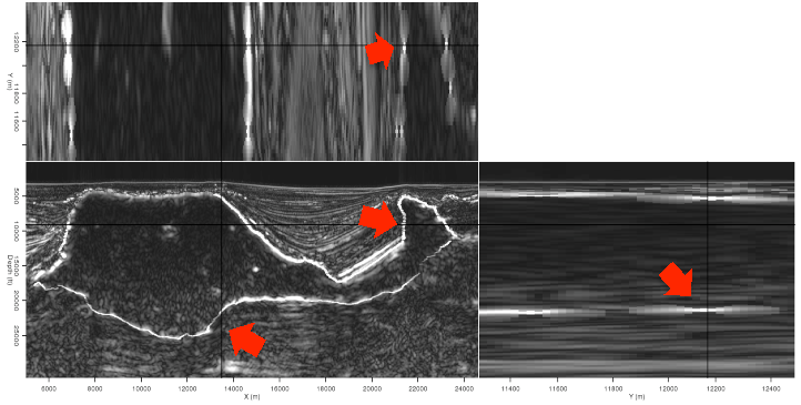
2d-merge,2d-topbase
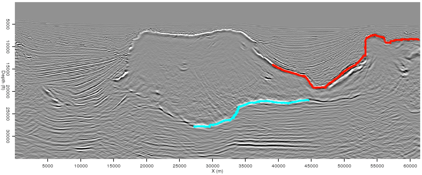
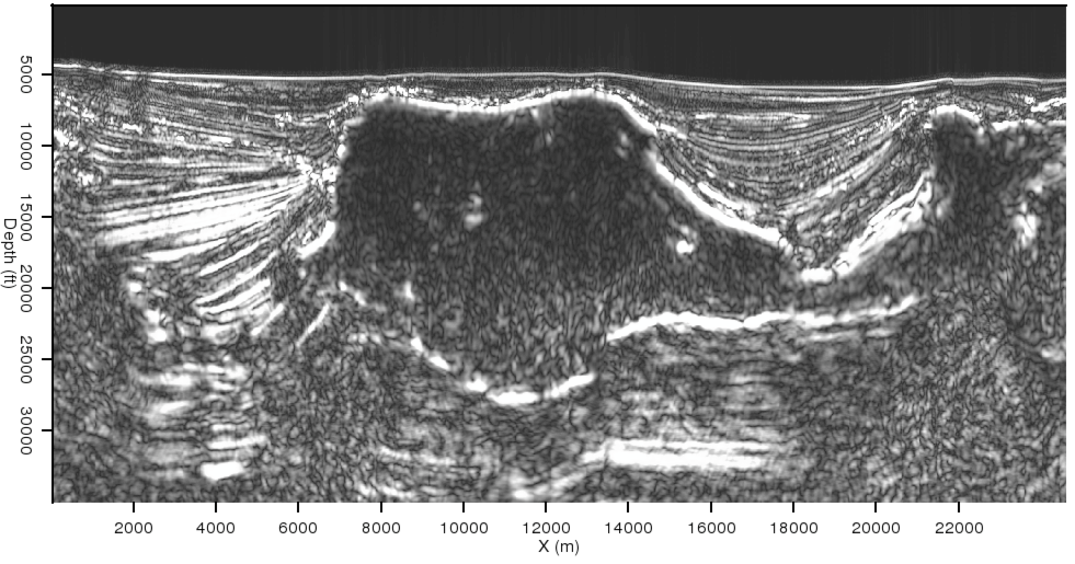
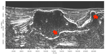
Figure 2. (a) 2D segmentation result without interpreter guidance. The salt body segment shows significant ``leakage'' at the locations indicated. (b) Manual interpretations of the salt boundary near where the leakages occurred. |
|
|
At this point, these manual interpretations must somehow be incorporated into the automated framework of the PRC method. Broadly speaking, this can be done in two ways. First, we can modify the algorithm itself to check for the manual interpretations when assigning weights to pixel pairs. However, this option adds unnecessary complexity to the process and would likely severely curtail the algorithm's efficiency (one of its major advantages). Alternatively, we could modify the input data according to the picks, and allow the segmentation algorithm to proceed normally. Since this option preserves the algorithm's efficient structure, I focus here on modifying the input amplitude of the envelope volumes to accommodate the manual interpretations.
|
|---|
|
2d-env-orig,2d-env-new
Figure 3. Amplitude of the envelope calculations from the original image (a), and modified according to the manual salt picks in Figure 2(b). The salt boundary is clearer and more continuous in the modified image, especially at the indicated locations. |
|
|
A simple solution to the problem would involve assigning a high amplitude value to the manually picked points. While this is the basic idea behind the solution described here, it is unfortunately not quite so straightforward. Assigning high amplitudes to a string of points without regard to neighboring amplitude values causes the algorithm to treat the manual interpretation as a segment distinct from those surrounding it, even those also inside a salt body. Instead, I define a new amplitude value ![]() for a ``picked'' pixel at position (x,y,z) in terms of the highest-amplitude pixel in a neighborhood surrounding it and a scaling factor
for a ``picked'' pixel at position (x,y,z) in terms of the highest-amplitude pixel in a neighborhood surrounding it and a scaling factor ![]() :
:
| (1) |
|
|---|
|
2d-merge-new
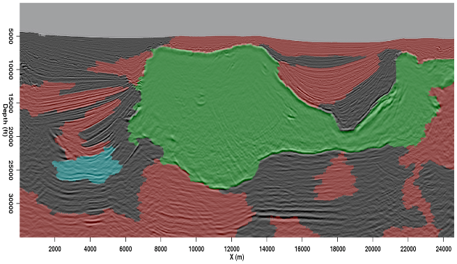
Figure 4. 2D interpreter-guided segmentation results. This result incorporates the manual picks seen in Figure 2(b). |
|
|
|
|---|
|
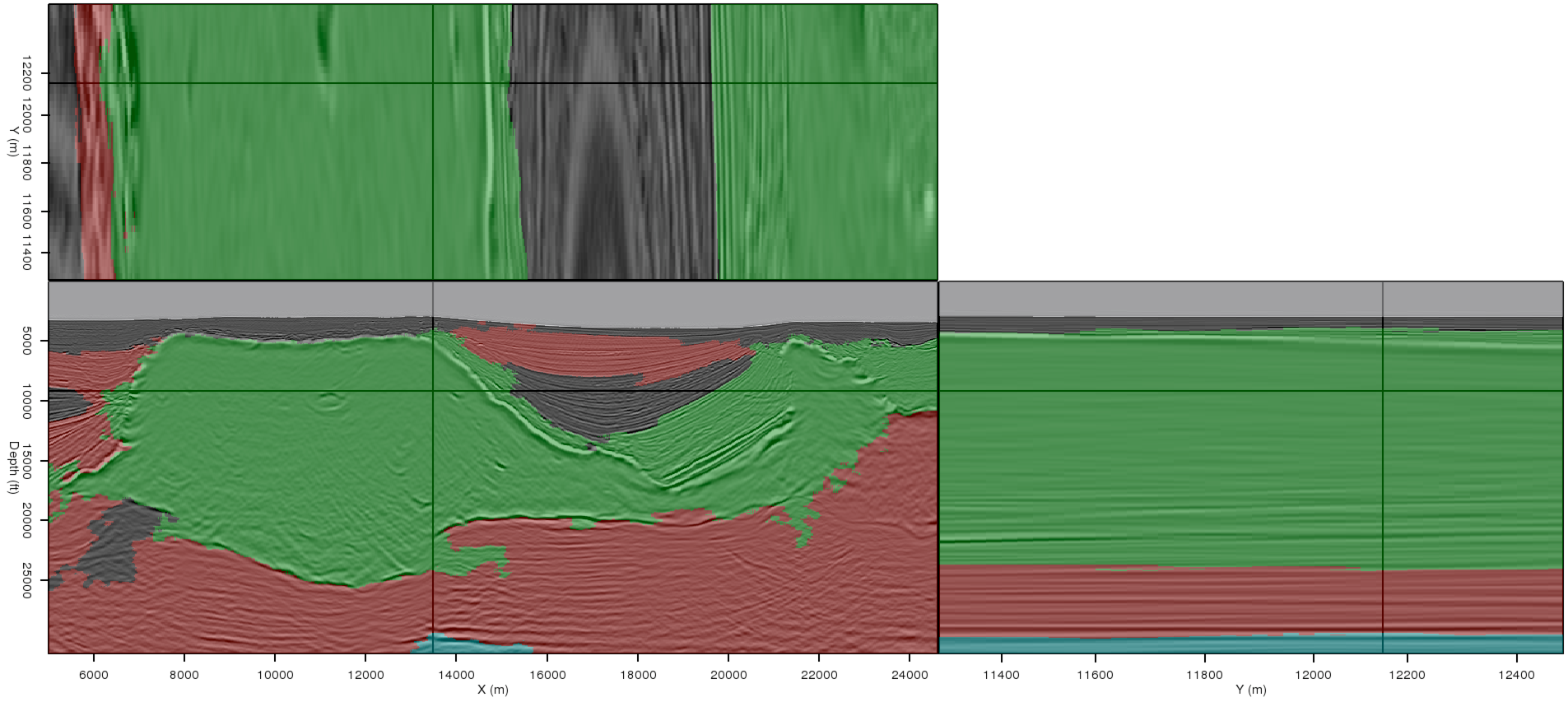
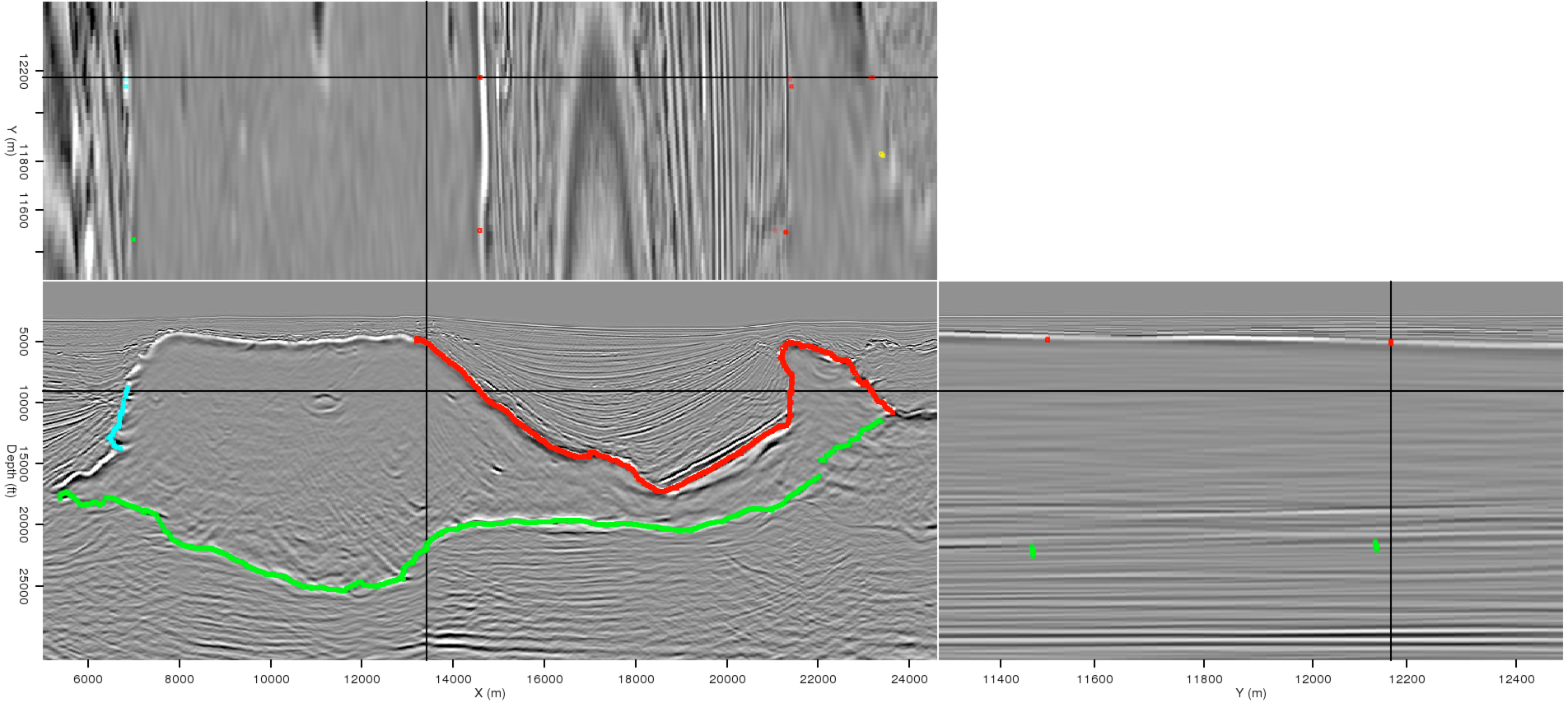
3d-origseg,oct-3d-picks
Figure 5. (a) 3D segmentation result prior to any interpreter guidance. (b) Manually interpreted salt boundary picks. Manual picks from one or more sections are used to guide the automatic 3D segmentation. |
|
|
|
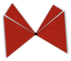
pyramid
Figure 6. Schematic illustrating the concept of ``spraying" manual interpretations of a 2D section into the third dimension. The black dot represents a pixel along a manually-picked horizon. |
|
|---|---|
|
|
|
|---|
|
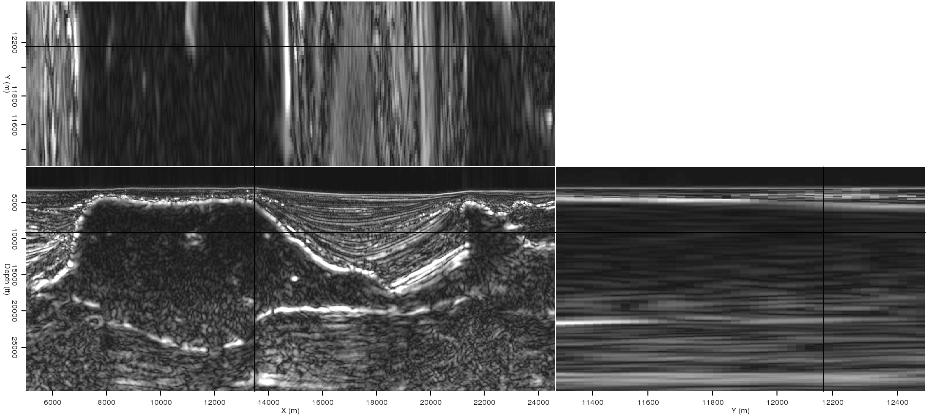
3d-env-orig,3d-env-new
Figure 7. 3D amplitude of the envelope calculations from (a)the original image, and (b) modified according to the manual picks seen in Figure 5(b). The 3D effects of the procedure to incorporate the picks are evident on the crossline and depth slices. |
|
|
|
|---|
|
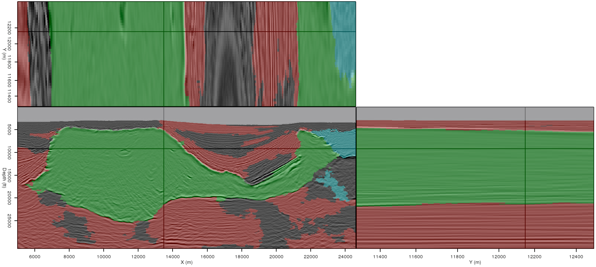
3d-newseg
Figure 8. 3D interpreter-guided segmentation results, incorporating the picks seen in Figure 5(b). Note that in this result, the segmentation is more accurate in all three directions. |
|
|
|
|
|
|
Interpreter input for seismic image segmentation |